Continue to Site

Welcome to our site!

Electro Tech is an online community (with over 170,000 members) who enjoy talking about and building electronic circuits, projects and gadgets. To participate you need to register. Registration is free. Click here to register now.

  • Welcome to our site! Electro Tech is an online community (with over 170,000 members) who enjoy talking about and building electronic circuits, projects and gadgets. To participate you need to register. Registration is free. Click here to register now.

DIY Generator

Status
Not open for further replies.
williB said:
Ok got the last two done..
Ya know , this will just fit in the size of a 3 1/4 '' hard drive case ..we'll see.. :lol:
now the question arises ( if i decide to put it in the 3 1/4 '' ), how am i gonna apply power to it? A while back i got this cranking flash light with a bunch of gears in it..possibilities..

Willi, looking at the pics of your ciols I thought you might be interested in a trick I found to get real slim coils.
As you know the air gap is the real killer in power output with these PM alternators. A smaller air gap results in a many times stronger magnetic field for the coils to pass through. You can get around this to some extend by using stronger magnets but these are bigger, making the whole assembly bigger too. Going the other way, by using very slim coils for a minimum air gap, you can increase the magnetic field of magnets of the size you used.

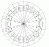
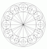
What is needed is a slim coil assembly with a wire gauge/ max turn compromise. With conventional coils you immediately have the problem of routing one wire from the inside diameter to the outside, adding a one wire thickness to the coil which contributes nothing to the coil output and widenes the air gap.

What I have used are two slice pancake coils. These have less turns (only two slices) than the conventional coils like yours but the adventage of having BOTH wires finish at the outside of the coil.
How is it done? You make a former exactly two wire sizes wide. You figure out how many turns you can get in one 'slice' and calculate the mean wire length. You double this for the second 'slice' and add for the pigtails.
Cut a piece of wire of this length and find the middle of it. Start winding the two 'slices from the wire middle at the bottom of the former. You keep wrapping the wire ends in opposite directions around the former core, creating two 'slices' of coil as you go, with each 'slice' having the wire in a single vertical layer. You end up with both wires at the top and a VERY slim coil.
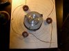
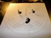
I used 5 min epoxy to lock the ends in place before removing the coil from the former. Handle the finished coils carefully when interconnecting and placing them on a layer of fibreglass cloth before casting the coil assembly.

I used a six coil assembly, over which another assembly was glassed at a 30 degree offset. This gave me an epoxy cast & glassed 12 coil assembly only 1/4" thick!
The 6 coils had 16 turns each and were all connected in series for a total of 96 turns per coil layer, giving 4 wire pigtails per complete asembly.

I guess there are many combinations of coil interconnection, most people use 3 phase technology, I'm aiming for 4 phase with two coil disk assemblies and triple rotors. This will use 4 bridge rectifiers to get DC output.

Klaus
 
As you know the air gap is the real killer in power output with these PM alternators.
I know , its proportional to 1/r^2 or something like that.. 8)
What is needed is a slim coil assembly with a wire gauge/ max turn compromise.
ya i'm allready thinking my 17 gage wire is too thick. but the appeal of lower resistance , is overwelming. :lol:
as pic 3 shows an 18 coil -24 magnet genny with six coils per phase ..
today i used six of my 9 coils to test out one phase ..
as it is i'm getting 0.5 ohms per phase! no voltage or current readings yet. as i have to adjust the air gap and afix the coils to the genny a little better..plus now i need nine more.. ug!..:lol:
That is a great idea , about taking half the wire and winding two layers , i wonder if it will work with coils of more than two layers ( mine are about 10 layers thick and six or seven layers wide ) ? which is really about only 15 feet total length..

Pic 1 is the placement layout centered on the board , i've since changed the layout to 18 coils which was as easy as adding a coil between each coil shown.
Pic 2 , is the hub from a 5 1/4 '' HD which has been my main bearing since i've been on this project.. :lol:

ps i really hate this LIFO approach to attachments..
 

Attachments

  • 18coil_24_magnet.gif
    18coil_24_magnet.gif
    26.8 KB · Views: 1,868
  • picture_102.jpg
    picture_102.jpg
    89.3 KB · Views: 1,896
  • picture_100.jpg
    picture_100.jpg
    81.1 KB · Views: 1,757
well i've been underestimating the speed of the excercise bicycle/ generator , while cranking the new pedal arrangment by hand i have some new numbers..
let me run them by yall..
on the scope is one complete cycle , with it set at 1mS/div,the wave takes up 7 divisions..0.007s/cycle..
1/.007 = approx 142 cycles / sec.
with 24 magnets i'm getting 12 cycles / rev.. not 24..
142/12 = 11.9 rev/sec
multiply by 60 sec/min gives 714 RPM !!
i've got some numbers for one phase of the genny , i've cut the gap in half , at least, but still could be better, and i've got 7 of the 12 remaining coils done 18 total , but havnt put them in yet ..
i am getting 18 V peak to peak and ran some numbers on the expected output ..

' Y ' connected 3 phase line to line Volltage = (Vp/sqrt(2))*sqrt3..
Vp / sqrt(2) = Vrms
Vrms * sqrt(3) = line to line V.. i think??
anyway it comes to 11.02V calculated , no load .. a little dissapointing to say the least..
 
Have you tried comparing a ready made dynamo or alternator?, or even a simple DC motor used as a dynamo?. All the results you've posted so far look pretty poor, why not use a ready made generator?.
 
no i havnt tried a dc motor/generator ..
i'm gonna keep plugging away , i wouldnt say all the results so far are poor..
with the single phase generator i was getting a lot more voltage but the coils were bigger .
i've ordered some 20 gage wire ( .032 '' ) which should give better results for a three phase genny..
 
Like a guy on another electronics chat forum who wanted to use a computer fan as a generator to power many LEDs and charge Ni-MH cells on his bicycle.

The fan actually powered a single LED very dimly when he was going as fast as he could go downhill. It would take weeks to charge his little battery.

I suggested reversing the connections so the little fan was powered from his battery and it could propel him along. Its thrust was about 10 grams. :lol:
 
williB said:
no i havnt tried a dc motor/generator ..
i'm gonna keep plugging away , i wouldnt say all the results so far are poor..
with the single phase generator i was getting a lot more voltage but the coils were bigger .
i've ordered some 20 gage wire ( .032 '' ) which should give better results for a three phase genny..

It's not voltage that's important, it's power!, all the results you've mentioned so far are only very low power. Remember the little DC dynamo's you get on push bikes?, they produce enough for the lights whilst taking very little effort from the rider.

I'm very impressed with the effort you're putting into it, but the results are rather disappointing.
 
Whew !!
almost done !!
it still needs a little tweaking, like adjusting the air gaps .
i ran out of brass screws , and had to use stainless.
and i still have to solder some of the connections.
this is my first 18 coil 24 magnet three phase generator !
the last phase was the easiest to attach because there was only one spot left to put the coils :lol:
 

Attachments

  • picture_105.jpg
    picture_105.jpg
    130.8 KB · Views: 1,615
Big mess of wires. :lol:

You have to triple check here to make shure evrything is wired up right.

The easyest mistake to make is conecting the coil the worng way round becose bouth wires are identical.
 
Well the results are in..
I was close when i said the open circuit voltage would be 11v it is actually 12.5 to 13.05 Volts depending on which meter i use ..
the measured resistance of each phase is 0.5 Ohms and the line to line resistance is 1.0 ohms..
all measurements are DC and are recitfied with six diodes, and all current measurements are taken with the meter on the 10A scale..
into a 1 ohm resistor at one speed i got 3.9V @ 4.05 A = 15.75 W
at a faster speed also into a 1 ohm resistor i got 4.16V @ 4.28A = 17.8 W
and with the output going directly into the meter on the 10A scale 6.67A @ 1.97V = 13.14W
not too shabby for (24) 1/2 '' magnets and some wire ..
I cant wait till the 20awg wire gets here..
 
Watts (what's) the efficiency? A couple of hundred watts of work to get 15W out?
 
I've found a new source for Neo-Magnets, but havnt tried them yet..
https://www.magnetsrc.com/neo_NdFeB_magnet_disc_magnet.htm

below is a new generator designed with 7/8'' dia x .5'' magnets, it should give , an open circuit , output of at least 32 V with 20 AWG wire , current estimates are unknown at this point .. :lol:
oh the coils are 1.75'' dia., twice the magnet dia..
 

Attachments

  • seven_eighths_magnets.gif
    seven_eighths_magnets.gif
    22.1 KB · Views: 1,187
williB said:
How would you test them ?
ps my apologies audioguru

How about 'the perpetual motion way'?.

Use a DC motor to spin your generator, monitor the current to the DC motor and the voltage across the motor - simple VxI gives you the input power to the drive motor.

Apply varying resistive loads to the output of the generator, again monitoring both current and voltage (FOUR multi-meters would be useful here!), simple VxI gives you the output power. You should be able to find a load value that gives the most power (largest VxI). It will give you the opportunity to post some more nice diagrams, this time of the load versus power graphs.

By comparing the input power and the output power, and at different load levels and speeds, you can get an idea of how efficient it is. Using different speeds might be informative as well?.

Obviously, this introduces the unknown efficiency of the drive motor, but you can ignore that as you're not wanting absolute values, just a comparative test of which might be better.

As I mentioned previously, try a commercial dynamo or alternator, or a DC motor backwards, and see how your generators compare - if you're not beating them it's rather a pointless exercise? - but VERY educational!.
 
Nigel , i think that sounds like a lot of work .. and to what end?? i know it works.. and works well..!!
 
williB said:
Nigel , i think that sounds like a lot of work .. and to what end?? i know it works.. and works well..!!

I thought you were trying to make subjective tests?, but perhaps you're not bothered about how well it works? - as long as it works well enough!.
 
Willie,

At the risk of having missed the point somewhere here, there are two things which seem to be wrong with your generator.

The rather odd ratio of magnets and coils, I would have expected a ratio of 1:1 or 2:1, but I am not an expert on 3 phase genrators.

What are the coils mounted on? it looks like a wooden board, and they are held on with brass or stainless steel screws.
What are the magnets mounted on? I cannot tell.

You have a serious problem here, there is no magnetic circuit!
Have a look at (say) a simple permanent magnet motor. There will be two iron poles from the magnet. The poles are very close to the rotor, a very small air gap, and the rotor is its self made of iron.
Lots of magnetic material to make a magnetic circuit.

What is in your magnetic circuit? several inches of air and wood. Not good.

JimB
 
Hiya Willi,
As Jim stated above, it looks like you've mounted everything on plywood and not steel. All the stators I've looked at are suspended in fibreglass and held stationary. The magnets are mounted onto a disc of 3/8" minimun as this lets the flux generatored from the magnets to flow. This has been talked about heaps on the otherpower forum and atleast I find by reading otherpower posts I can avoid their mistakes and make up a working unit in 1 go.

Cheers Bryan :D
 
Status
Not open for further replies.

Latest threads

New Articles From Microcontroller Tips

Back
Top