Continue to Site

Welcome to our site!

Electro Tech is an online community (with over 170,000 members) who enjoy talking about and building electronic circuits, projects and gadgets. To participate you need to register. Registration is free. Click here to register now.

  • Welcome to our site! Electro Tech is an online community (with over 170,000 members) who enjoy talking about and building electronic circuits, projects and gadgets. To participate you need to register. Registration is free. Click here to register now.

DIY Generator

Status
Not open for further replies.

williB

New Member
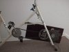
I can finally crack the 2A barrier with my DIY Generator..
I hooked it up to an excercise bicycle..lol with a four to one chain drive..!!
If i can find another 2:1 sprocket set , will that be 6:1 or 8:1 final drive ?? 8:1 i think..
Anyway i am now the proud owner of a genny-ciser or exer-gen.. :lol:
Preliminary results are VERY nice.!!
I did a test with a FWB rectifier setup and with no trouble at all i was able to max out my meters 2A scale .. i just thought about the 10 A scale , wow cant wait to try it..
I also tested an 1156 brake light bulb and it was very brite.. :lol:

::edit::
For anyone reading this for the first time i've made a little table of values you could expect for the varibles given..
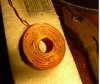
the coil diameter is 1 inch . the hole is just under 1/2 inch @ 0.480''
if you have any questions please let me know..

Code:
         RPM   OHMs/coil   turns/coil  V peak to peak (no load)  

17 AWG   833    0.1            60             3
21 AWG   833    0.4            150            8

note : this is for just one coil page 4 has my current 18 coil 24 magnet generator
 
I seem to remember (fairly vaguely) that a 100W bulb is just about sustainable from a bicycle driven generator? - but probably NOT for someone as unfit as me these days :lol:
 
Nigel Goodwin said:
I seem to remember (fairly vaguely) that a 100W bulb is just about sustainable from a bicycle driven generator? - but probably NOT for someone as unfit as me these days :lol:
:lol: more to come in the next few days .. but i gotta get outside and enjoy this beautiful day..
 
Sounds good. Share what you've done when you have time.

You've not mentioned the voltage but keep Nigel's comment in mind. If the total power ouptput at 2 amps is significantly more than a fraction of a horsepower something might be wrong with your measurements. Now, 2 amps at 12 volts makes sense so I am not saying that 2 amps is wrong.

Anyway, I'd be interested in seeing the arrangement if that's possible.
 
Soon your generator will provide enough power to supply a motor to propel a bicycle! :lol:
One guy did that with his generator driving a computer fan for propulsion, or maybe it was the other way around, his fan was the generator that drove the motor to propel his bike.

I know, perpetual motion is impossible.
 
stevez said:
Sounds good. Share what you've done when you have time.

You've not mentioned the voltage but keep Nigel's comment in mind. If the total power ouptput at 2 amps is significantly more than a fraction of a horsepower something might be wrong with your measurements. Now, 2 amps at 12 volts makes sense so I am not saying that 2 amps is wrong.

Anyway, I'd be interested in seeing the arrangement if that's possible.
I believe nigel was talking about the maximum sustainable human output power from a stationary cycle ...yes ?...
the 2 A was not at 12V though as i was seeing what i could put into a resistance of .33 ohms ..
at 2 A i got a voltage of 1.36 V into a measured 0.4 ohms..
V^2/R gives 4.62Watts
but V*I gives only 2.72 Watts
i dont own an AC Ammeter, but i would be interrested to see what is comming out before the diodes..
Pic 2 is a close up of the actual generator..
 

Attachments

  • picture_033.jpg
    picture_033.jpg
    89.3 KB · Views: 3,049
  • picture_032.jpg
    picture_032.jpg
    116.9 KB · Views: 2,933
williB said:
I believe nigel was talking about the maximum sustainable human output power from a stationary cycle ...yes ?...

Yes.

the 2 A was not at 12V though as i was seeing what i could put into a resistance of .33 ohms ..
at 2 A i got a voltage of 1.36 V into a measured 0.4 ohms.

How did you measure the 0.4 ohm?.

V^2/R gives 4.62Watts
but V*I gives only 2.72 Watts

If you get different values (particularly as wildly different as that), then you've measured wrong somewhere. Certainly the most difficult to measure is the resistance, which is why I asked above. Assuming the voltage and current are measured correctly, then the resistance is 0.68 ohms.

Only 2.72W though is pretty poor?, it's less than you get from a standard bicycle dynamo!.

i dont own an AC Ammeter, but i would be interrested to see what is comming out before the diodes.

I wonder how accurate you existing meter is?, as you're not feeding it smooth DC, but essentially double frequency AC that only moves one way from zero - a normal meter isn't going to read that correctly.
 
there are currently 6 coils on the generator , two are wound with #17 gage wire , one is #19 gage wire , and the other three are #22 gage..
i have room on there for six more coils.
i have two more coils of the #17 gage wire allready made ,but not on the generater..
 
How did you measure the 0.4 ohms
total measured resistance minus the meters tip to tip resistance
1.3 -0.9 = 0.4

I wonder how accurate you existing meter is?, as you're not feeding it smooth DC, but essentially double frequency AC that only moves one way from zero - a normal meter isn't going to read that correctly.
thats probably why..
you are correct , there was no smoothing whatsoever at the time of the test..
EDIT::eek:
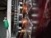
ne more thing there are 22 Neodium(sp) Magnets 1/2 " dia X 1/2" long
therefore i can only add 5 more coils for a total of 11.. hooked in series ..
 
Hiya Willi,
Eh mate hooking up those coils in series is probably causing most of your problems. Question have you read up on otherpower and Hugh Piggots book on alternators. All of the alternators I've been studying are hooked up in 3 phase in either star or delta configaration. I'm no guru on this by far but using different diameter wires on you coils could be effecting the flux generated from the magnets and cancelling out most of it. I'm sure if you posted this up in otherpower then they would be a few more people wth greater knowledge to help you out, takin nothing away from this forum mind you. Anyways it's looking good so keep us posted. :D

Cheers Bryan :D

P.S. Update on my wind genny project, yesteday I poured the slab for the tilting tower base, so Im a little closer to getting it up and flying
 
What i need is another sprocket set , which will give me an 8:1 ratio..
here is why
pedeling really slow gives me a 100HZ on the genny as it is , with very little , to no resistance ( to my pedeling)..
now if i can get 8:1 sprocket ratio , that slow speed pedeling will be 200HZ , and more importantly will hopefully provide just enough resistance to make it fun.. :lol:

Bryan1 i will try the 3 Phase ( star configuration ), i'll have to reposition the coils though..not a big deal..as they mostly are hot glued on there..I'll also need at least one more coil ..totalling nine..
a 150% efficiency increase , over single phase,would be nice,
the delta config. I believe requires to much speed to work effectively..
I added two more coils lately,total 8, and i am charging 5 NiMH batteries in parallel ..
on a side note , as soon as i start cranking the meter jumps right up to an amp. and has been up to 2.2 A at various times..

williB
 
I've done some conversions and calculated the 100HZ to RPMs..
There are 22 magnets which produce 22 peaks per revolution..
so 100/22 = 4.5 rev/sec .
4.5*60 = 270 RPM
if i double the sprocket ratio this will give me 540 RPM .. :D
EDIT :: i was wrong here because 22 magnets gives 11cycles per rev..not 22 .. so at this cranking speed i was really getting 545 rpm..
 
I'm still working on my portable generater..btw..
below is the layout for six x 1.5" coils with 12 x 1/2" dia. magnets..
wired in single phase should output around 24V AC p-p depending upon the speed of rotation and the gage of wire used..
imo 22 to 20 gage would be best , if you go absurdly thin , you get more voltage , BUT the wire resistance will be way too high to do anything useful..
 

Attachments

  • gen.gif
    gen.gif
    17.7 KB · Views: 2,100
hi Willi,
I'm building a small wind generator with a similar layout as you show. The difference being that my 6 ( pancake) coil stacks are arranged so that they almost touch each other. They are spaced so that when a magnet's leading edge just enters a coil's outer diameter its trailing edge just leaves the centre diameter of the previous coil, I read somewhere that this spacing is the most efficient for PM poles.

I'm also using two sets of pancake coils per coil assembly, second is offset to the first The magnet rotors have 10 magnets on each side. It all gets quite complicated mechanically as there are 3 PM rotors (40 magnets total - centre one has magnets on both sides) and two coil disks placed between the rotors with minimal air gap. The pancake coil disks assemblies, holding 2x6 offset coils, are just 6mm thick.

I never bothered about the star delta business since the end result is DC anyway. It is far easier to just connect the coils in series with such a thin assembly.
So, each set of 6 coils is connected in series for a total of 96 turns and the two ends of each coil bank go to a bridge rectifier which should give me a fairly low DC ripple at the paralleled DC ends of the 4 bridges.
The coil wire size is 1.1mm, whatever gauge that corresponds to, I used what I had with a compromise of low resistance and the ability to cram turns into flat coils.

I wish I could post test results of this arrangement but I'm still getting ready to cast the aluminium endcaps which will hold the bearings after machining them. I would be happy to get around 200W from a 1m diameter prop.

Klaus


williB said:
I'm still working on my portable generater..btw..
below is the layout for six x 1.5" coils with 12 x 1/2" dia. magnets..
wired in single phase should output around 24V AC p-p depending upon the speed of rotation and the gage of wire used..
imo 22 to 20 gage would be best , if you go absurdly thin , you get more voltage , BUT the wire resistance will be way too high to do anything useful..
 
Klaus,
I shifted the coils around in a tighter pattern , keeping the same number and spaceing of magnets..
This sure gets complicated !! , because , for my case anyway , i cant just add two coils and expect it to work ..as you can see , its not gonna work..
i'm gonna try a different number of magnets.. :lol: i'll get back to ya...
1.1mm wire is 0.043 " its between 17 & 18 Gage , good thick wire..

Brayn you were correct.. :oops:
i did a scope test of individual coils in the generator under load..
the 17 Gage wire turned out a perfect sine wave , while the coils of the thinner wire , were somewhat distorted..
I guess ya cant mix coil wire diameter in the same generator, who would have thought ?? :wink:
 

Attachments

  • gen2.gif
    gen2.gif
    15.6 KB · Views: 2,142
Hiya Klaus,
Eh mate that design ya doing sound interesting, do you mind putting up a few pic's of the alternator as it will be good veiwing. When you say your only going to have a 1 metre diameter prop that sounds way too small for a wind genny. I have a spreadsheet that tells you the T.S.R. (tip speed ratio) for a given blade diameter and expected wind speed, the ideal tsr is around 5 to 7 off memory, if you like I can send the spreadsheet to you so you can try out a few different combinations. Also have you ever checked out the otherpower forum as some of the blokes on there are wind genny guru's and don't mind answering questions thrown up on there. As far as not bothering about 3 phase star or delta configaration have a good read up on that forum and I reckon you'll soon change your mind. Off what you describe with your project, setup correctly I'd be surprised if you didn't get 750 watts atleast. Also I found a contact in Oz for 30x40x10 neo magnets and Hugh Piggot's book for around $200 and thats with 24 magnets. Anyway if I can helpout in any way Klaus I'd be happy to. :)

Cheers Bryan :D
 
Gday Bryan,
The 1m diameter is more practical on a boat where I plan to use that thing if I ever get it finished. I have read most of the wind power sites on the net, 200W would be all to be had from such a small prop. I will delve into that tip speed thing when the alternator is up and running, plan to test it on my lathe first to see where the best output falls with regard to RPM. The prop will then be tackled, no point making it first when I do not yet know the performance curve.
The magnets I'm using are quite small to keep the lot compact, again lessening the output and hence the 3 rotor idea to get all it inside a 120mm diameter.
I am an electrician but presently an electronic technician so the have or have not 3 phase question is a familiar subject.

I did take some pics as I go along with the building process, presently have them up to casting the coils into epoxy. Send me a private e-mail to: norbert3008@msn.com with something obvious, like windpower,etc. in the subject line and I'll pass the pics on to you.
Klaus

bryan1 said:
Hiya Klaus,
Eh mate that design ya doing sound interesting, do you mind putting up a few pic's of the alternator as it will be good veiwing. When you say your only going to have a 1 metre diameter prop that sounds way too small for a wind genny. I have a spreadsheet that tells you the T.S.R. (tip speed ratio) for a given blade diameter and expected wind speed, the ideal tsr is around 5 to 7 off memory, if you like I can send the spreadsheet to you so you can try out a few different combinations. Also have you ever checked out the otherpower forum as some of the blokes on there are wind genny guru's and don't mind answering questions thrown up on there. As far as not bothering about 3 phase star or delta configaration have a good read up on that forum and I reckon you'll soon change your mind. Off what you describe with your project, setup correctly I'd be surprised if you didn't get 750 watts atleast. Also I found a contact in Oz for 30x40x10 neo magnets and Hugh Piggot's book for around $200 and thats with 24 magnets. Anyway if I can helpout in any way Klaus I'd be happy to. :)

Cheers Bryan :D
 
well i got two coils done tonight .. :D
the coil in the first pic is made of 17 Gage enaml coated wire, 1.5" dia. by 1/2" thick with a 1/2" hole..

the second pic is my fixture with the second coil just finished and still curing.. 8)
anyone recogneze the " fixture " is really a gas line tube bending device :lol: which i bought a while back at pep boys..that glossy finish is polyester resin..
on previous coils before tonight, i would just start wrapping the wire around the center with the starting wire dangling out , But this 0.045" wire would get in the way , and cause the wire to bulge out around the protruding wire..anyway tonight i filed a slot for the wire in the center sleve , and wrapped the pigtail end around the bolt, then after i poped out the center sleave i unwound the wire ..
thats the only way to get a good winding , imho
 

Attachments

  • coil_fixture.jpg
    coil_fixture.jpg
    35.2 KB · Views: 1,619
  • coil_161.jpg
    coil_161.jpg
    30.9 KB · Views: 1,694
Hiya Willi,
Eh mate in all the wind genny coils I've seen they all have been sorta pear shaped but there's nothing to say a round coil wouldn't work as good. I suppose since your using round magnets it should be ok. I'm in the process of designing up a coil winding jig but I'm waiting on the 1/8" cube neo magnets I bought turning up. These magnets will be used with a hall effect sensor and I'll program some of my older pic chips to decode the pulses and output it to a few 7 segment displays.
Anyway with the ****** rain we've had over the last day and expect tommorow I'll have to wait to finish doing the anchors so I can finally get my wind genny flying and I'm waiting to see the best price I can get for 25 2"x1"x1/2" neo's so I can get going on my honda disk brake genny :twisted: Well they do reckon Honda's go faster :twisted: :twisted:

Cheers Bryan :D
 
Eh mate in all the wind genny coils I've seen they all have been sorta pear shaped but there's nothing to say a round coil wouldn't work as good. I suppose since your using round magnets it should be ok.
Exactly .. The coil should take the shape of the magnet , within reason..
the rectangular magnets have pear shaped coils . ideally the inner part of of the rectangular magnet should/would be tapered down..
I got 2.8A from the genny today , after i swapped the two smaller dia wire coils with the two new 17 Gage coils ..what i did was connected the genny to a full wave bridge Rectifier then connected that to a DC Ammeter..two more ta go and all will be 17 gage wire :lol:
I also took more pics and a movie but hav'nt put them into the puter yet..
 
Status
Not open for further replies.

Latest threads

New Articles From Microcontroller Tips

Back
Top