Electro Tech is an online community (with over 170,000 members) who enjoy talking about and building electronic circuits, projects and gadgets. To participate you need to register. Registration is free. Click here to register now.
Welcome to our site! Electro Tech is an online community (with over 170,000 members) who enjoy talking about and building electronic circuits, projects and gadgets. To participate you need to register. Registration is free. Click here to register now.
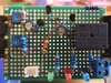
You say the bread board wiring works. I noticed that there are no LEDs on that. I see three 10KΩ resistors on the bread board but only one on the perf board. So your perf board(s) are not the same as you bread board.
That was one board. i removed the 10k resistor from the delay on because i did not need it. the 50k pot had enough delay. i did make another where i included all the components. im just so puzzled by this.
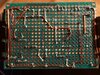
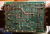
what can i test to determine why the relay will not trip (delay on). here is the current board.
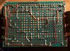
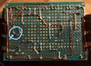
I added documentation to the back of the circuit board (pic 112234)
That was one board. i removed the 10k resistor from the delay on because i did not need it. the 50k pot had enough delay. i did make another where i included all the components. im just so puzzled by this.
Don't make another perf board. It gets very confusing.
So a little trouble shooting with your DMM on the 20VDC scale. I will use the schematic in Post #75, You choose the perf board we will refer to.
1. Attach the (+) probe to the +12v rail. Leave it there for now. You are going to measure with the the (-) probe. The measurements will be directly to the components' leads, not at wires connected to it.
2. With the power off, what is the voltage at the (-) terminal of C1?
3. Apply power. Did the green LED light? What is the voltage at the (-) terminal of C1?
4. Press and hold the push button switch. Did red LED light? What is the voltage at the (-) terminal of C1? Does it ramp up from 0V toward +12V?
5. Release switch and repeat 4. Do you see the same thing at the emitter of Q2.
6. Release switch and repeat 4. Do you see the same thing at the end of resistor R4a that connects to Q2e and C1(-)
We will walk through this step by step as I get your responses.
Thank you for this.
When I set up to test the components the circuit came to life and closed the relay. i opened the switch and 6 seconds later the relay opened. I was shocked and excited. My first thought was why is it working? I probed the back of the board for poor solder joints but all i could find was that I jumped the 200k pot (shorted) so only the 47k resistor was active. That explained why the off delay would not exceed 6 seconds. Ironically my Sketch shows the same short. So i actually wired it up just like my drawing. I corrected the short. Now the delay on is such that even if I turn the 50k pot to 0 the minimum on delay is 5 seconds. I would like to see 1.5-2 seconds so im going to replace the 10k resistor with 5.1k. I have tested the 50k pot and it does work. This is probably the reason i removed it from my breadboard.
Im going to make a few of these boards and then finish the plexiglass boxes that will house the board, halo switch, SSR, outlet, and override switch.
thank you again.
Thom B.
Project complete. I made 3 complete kits for my planer, chop saw, and shaper. Thank you all so very much for helping with this. These files should help anyone who would like to build this.
Looks great but the use of acrylic (Plexiglas) as an electrical enclosure is not a great idea. It depolymerizes into volitile monomer and burns easily. Modern boxes with UL approval are available at the home centers. Usually made of Polycarbonate or Polycarbonate+ABS blend with proper fittings for cable restraining connectors.
Plexiglass is flammable and starts burning at temperatures from 450 ° Celsius.
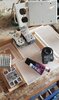
This is what I could find for this type of acrylic. I know you cannot tell from the pictures but this is 1/2" thick marine grade plexiglass. I got it from my father who got it from his father who stole it from a shipping yard. That was probably 70 years ago. I have used this for so many projects. I do appreciate the info. Im going to try setting this stuff on fire and see what happens but seeing how well this particular sheet has lasted through the years and compared to the quality of materials used these days I do think this stuff is the least flammable item in my workshop.
I took a small sample of this outside and hit it with a heat gun. it would not catch fire but it did warp significantly. I applied the flame from a blow torch and after about a 1/2 a minute it stayed lit and burned on its own. The manufacture says this will form droplets of burning plastic but this did not. Instead it burned more like a candle but with no smoke. it appeared to be evaporating. After 2-3 minutes I extinguished the flame and it had virtually no traces of charring. I also took a UL approved electrical box cover and did the same. This product would not catch fire but it produced a thick black intoxicating smoke. My father said the shipping yard his father worked at was under a military contract. I did read that there are different grades of Plexiglass but I would not know what grade this material is.
Flame Retardant Polycarbonate sold into electrical applications has a UL 94-V0 rating, similar to printed circuit boards (FR4). Self extinguishing on a horizontal surface. Acrylic has no UL94 rating that I know of but thick material may pass because of the heat capacity of the part before combustion. Generally a flame retardant plastic is selected but design can also be used to make parts take longer to burn. Like my 1.5" maple workbench. Maple twigs and sawdust ignite easily but a soldering iron will never be enough to set off a thick flat surface like my workbench.
Its been a while since you helped me make this Workshop circuit. Since then ive gained some experience using PCB software. Ive made (with help from this group) a Timer circuit for my closet and had PCBs manufactured and they look and work great. Ive even created PCB parts for my projects. Many of them for the workshop circuit. it took a long time but it was worth it. I intend on having 5 boards manufactured for my shop but before i send off the project I would like you to take a look at it and tell me if anything is wrong. When i originally did this project i was unsure how to properly wire a Variable Resistor. I used only 2 of the three pins. I learned of my mistake when working on another project. this is probabally why the timing of my build was not as you documented it.
Its been a while since you helped me make this Workshop circuit. Since then ive gained some experience using PCB software. Ive made (with help from this group) a Timer circuit for my closet and had PCBs manufactured and they look and work great. Ive even created PCB parts for my projects. Many of them for the workshop circuit. it took a long time but it was worth it. I intend on having 5 boards manufactured for my shop but before i send off the project I would like you to take a look at it and tell me if anything is wrong. When i originally did this project i was unsure how to properly wire a Variable Resistor. I used only 2 of the three pins. I learned of my mistake when working on another project. this is probabally why the timing of my build was not as you documented it.
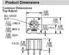
A pot (potentiometer) is a three terminal device. It has two pins that present a constant resistive path between two pins, and a third pin (called the "wiper"), that can be adjusted such that the value present at this pin is somewhere less than the total resistive value. For example, a 1k ohm pot. The total (constant) value between two pins is 1k, but the value measured from the wiper pin to each of the other pins will be a difference of the two values (somewhere from 0 to 1k). The potentiomenters in your schematic reflect a pot configured as a variable resistor so.....as long as you know which pin is the wiper, then you can connect it such that it functions as a "variable resistor" instead of a pot. You just connect the "wiper" to one end of the pot. The pots on your PCB look to be connected correctly...or at least as shown on your schematic. But the only way to know for sure is to check the part datasheet, measure the part with a meter, or look for a graphic on the part itself that indicates which pin is the wiper.
The graphic on the part looks something like this:
Pin 2 (the middle pin) is the wiper pin
The only other consideration is how you want the pot oriented relative to increasing or decreasing its value. For example, a pot can be used in a lamp dimmer. If I'm oriented such that I'm facing the pot, do I want the lamp to increase brightness when I rotate the pot clockwise? or when I rotate it counter clockwise? Most would want to increase brightness when rotated clockwise. You can set this by changing the connection from the wiper to one of the other of the two pins if the rotation isn't correct.
Thank you. I know the pots configuration. I have them orientated so the rotation is logical (clockwise goes from 0 to 50k). So do i have them configured correctly is the next thing to figure out.
So i now understand if i disregarded the wiper and configured it using just pins 1 and 3 id pretty much have a 50k resistor. adjusting the pot would have no effect. and since i also have a resistor (R1) connected to pin 1 the total resistance is VR1 + R1.
So i now connect R1 to pin2 then pin1 of VR1 to create a variable resistor. I was also told that connecting R1 to pin1 then pin2 would achieve the same behavior. to me it looks like with this set up the resistance would increase as i rotate the pot clockwise.
The other pot VR2 appears to be configured differently. pin2 is connected to pin3 and not pin1. I want to say that this configuration would behave differently but im not sure. Since you say its all about the orientation so as long as i know which way is up "so to speak" and as long as i utilize pin2 and connect to pin1 or pin3 then both VR1 & VR2 would increase resistance as i rotate them clockwise.
But you do say the connection from pin2 to pin1 or pin3 can affect the VRs behavior.
Ive updated the pcb. relocated Q2,C1 and a few labels.
OK i did not realize how simple it was to test the pot with a meter.
if pin 2 is connected to pin 3 then resistance increases during clockwise rotation
if pin 2 is connected to pin 3 the opposite happens.
This site uses cookies to help personalise content, tailor your experience and to keep you logged in if you register.
By continuing to use this site, you are consenting to our use of cookies.

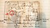
") I missed that error in wiring that pot too.
I missed that error in wiring that pot too.