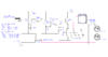
Continue to Site

Welcome to our site!

Electro Tech is an online community (with over 170,000 members) who enjoy talking about and building electronic circuits, projects and gadgets. To participate you need to register. Registration is free. Click here to register now.

  • Welcome to our site! Electro Tech is an online community (with over 170,000 members) who enjoy talking about and building electronic circuits, projects and gadgets. To participate you need to register. Registration is free. Click here to register now.

Auto Load Sensing Switch A/C

Status
Not open for further replies.
Modified schematic

Just a thought - how about posting pictures in a sensible format?, instead of the largest file sizes possible (BMP produces massive uncompressed files), it's not really a suitable format for anything, particularly posting images on a forum.

If you use PNG they are massively smaller, and lossless as well - best not to use JPG for images like these, as it's lossy and loses quality, OKMfor photos but not diagrams.
 
D1 and D1 are not needed. In your diagram D1 is shorted out. Back to your other question about the black capacitor, I don't know. The schematics were drawn after the fact many years ago. I've had to move files three times to new computers and all of the circuit board layouts have disappeared. If the external wall wart in a 12VDC regulated switch mode power supply you don't need C1. And if you are using a bigger relay than my reed relay, you need a diode across the relay coil. Cathode to positive (arrow pointing up).

Nigel,
I'll try to take the time to shrink what I post. I really liked .gifs for schematics, but the current photo editing programs on this computed don't give .gif as a SAVE AS option. I do find .png in PhotoShop.

GIF's were great, but PNG has pretty well replaced them - and Windows Paint can do PNG. But BMP is the worst of all worlds as it's completely uncompressed (handy if you're trying to display a picture with a micro-controller though).
 
.bmp is the export format for schematics in ExpressPCB, my electronics program. In the past Window's PHOTOS made am easy conversion. They improved it so SAVE AS is only in the original format. :(
 
D1 and D1 are not needed. In your diagram D1 is shorted out.
i figured as much. thank you for that.
it does look like the two blue caps c3 & c4 are 1000uF and not 100uF
shame about the mystery caps purpose. ill post it here in case someone wants to figure it out.
 

Attachments

  • RemoteSwitch5-1b2.jpg
    RemoteSwitch5-1b2.jpg
    992.2 KB · Views: 208
OK, I think I figured it out. The power supply to the left looks like it is from an unregulated DC wall wart. A 120 ohm 1/2w resistor, a diode and a capacitor on the board near the wire from that power supply tells me those three form a 12v Zener diode regulator. Like I said the schematics were drawn way after the fact.
 
UPDATED SCHEMATIC WITH COIL RELAY
please have a look. LMK if anything is wrong.
 

Attachments

  • Auto ON-OFF-R2.png
    Auto ON-OFF-R2.png
    23.1 KB · Views: 202
Neither are the resistor and diode next to it.
 
No I'm referring to the black cap, diode, and large resistor in the lower left corner In the attached.
Funny, I loaded the original photo (2.9 MBytes) into Paint. Cropped to just circuit board, pasted in a new image. Saved As an .png. And guess what? Its now it's 4.3 MBytes Resized it to 10%, and now 57KBytes

CircuitBoard2.png
 
Cropped to just circuit board, pasted in a new image. Saved As an .png. And guess what? Its now it's 4.3 MBytes Resized it to 10%, and now 57KBytes
You were most likely standing on the hose. :p
OK now i see that other diode hiding there.
I wanted to thank you for taking the time for me with this. It takes about 8 weeks to get some of the parts i need but i will make this and show you the results.
Thom
 
What parts take 8 weeks? :oops:
 
Because of viruses and the SNAFU state the world is in some shipments from hong kong are taking up to 50 days to deliver where last year it was average 14 days
What country are you in, the US?
You can get parts overnight from Digikey.com or in about three days for $9 shipping.

or in about a week for $3 shipping from taydaelectronics.com (good prices but some non-standard products from Chinese manufacturers). It all works though.
 
Last edited:
Current sensor and SSR are on eBay or Amazon. Ships in days.
 
Last edited:
Status
Not open for further replies.

Latest threads

New Articles From Microcontroller Tips

Back
Top