Continue to Site

Welcome to our site!

Electro Tech is an online community (with over 170,000 members) who enjoy talking about and building electronic circuits, projects and gadgets. To participate you need to register. Registration is free. Click here to register now.

  • Welcome to our site! Electro Tech is an online community (with over 170,000 members) who enjoy talking about and building electronic circuits, projects and gadgets. To participate you need to register. Registration is free. Click here to register now.

Auto Load Sensing Switch A/C

Status
Not open for further replies.
Ive ordered my parts. I plan on building two Delay Switches
A USA seller on Ebay accepted my bit for 2 Hawkeye 808H Current sensors. Similar to the 800H but with a sensitivity adjustment

These are the relays i will use in place of the reed style relays in the original design
Relay Spec Sheet
DPDT NA-12W-K 12VDC Toshiba
My power source is a wall wart (12V 200ma) I have another rated at (12V 500ma)

if you have any concerns for the coli relay and my power source please LMK
 
Both look OK.
 
Both look OK.
Thanks. it looks like the relay needs just 30mA to function.
Ive updated the schematic. Added 3 leds to monitor power, sensor, and relay. Ive got a AC double stack switch/outlet to replace the toggle override switch
 

Attachments

  • Auto ON-OFF-R3.png
    Auto ON-OFF-R3.png
    23.9 KB · Views: 207
UPDATE:
I finally got the remaining parts for this project. I was so excited i soldered one up on a board only for it to have a short somewhere. Even though I tested components for function my eyes are not good enough to see where i crossed a wire or two. I took a breath and bread boarded one up and it worked fine. Well almost. The on-delay is great 2-3 seconds and the 50k pot with the 10k resistor gives a tiny bit of play but not much. My issue seems to be the off delay. It has none. it just shuts off when i simulate an open circuit on the (-negative) side. Im going to post my picks and my schematic in hopes you can help me figure this one out. it could be that im not simulating the switch correctly but my readings show the circuit getting voltage where it should.

NOTE: Take a look at 2n3904 on my schematic. the pinout does not match that of the manufacture. i followed the manufactures pinout. AND on the picture i got from KMoffett does not look like a 2n3904. At least not like mine does.

thank you in advance for your help
 

Attachments

  • 3904ID.jpg
    3904ID.jpg
    2.1 MB · Views: 208
  • breadboard.jpg
    breadboard.jpg
    2.2 MB · Views: 212
  • Auto ON-OFF4.png
    Auto ON-OFF4.png
    31.4 KB · Views: 217
According to this link: 2n3904 pin#1 is the emitter and #3 is the collector. Maybe you simulator is in error. Other than that and the added resistors and LEDs, it it looks like mine and should work.
Ken
 
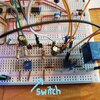
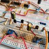
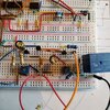
ok. thank you for replying. so you have no thoughts on why my breadboard mock would work on start delay but not on stop delay?
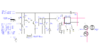
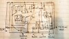
i know in your drawing you had options for the fixed resistor, pot, and cap. i used a fixed 10k, 0-50k, and a 100uf cap for the on and a 10k fixed, 0-200k pot, and a 100uf for the stop.
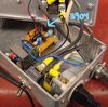
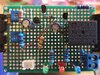
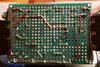
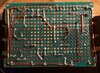
im ready to solder this up. i have made two plexiglass boxes to hold everything. did everything possible to separate the 110 from the 12v
 
You have the contacts of the current sensor connected so it interrupts the power ground to the output control relay, rather than just acting as a signal to the timing circuits.

As soon as that opens, there is no power to the right half of the circuit.

It should only be controlling the charge / discharge of if timing networks and not power to anything.
 
THANK YOU for the feedback. ive been trying to understand this with no luck but i do agree that where the switch is placed is the key to this working properly. if you could suggest a location for the sensor switch i would appreciate it. thank you.
 
rjenkinsgb is right. Note where the common is attached in my circuit. Attached.
ShopVac Delay Original.jpg
 
You have the contacts of the current sensor connected so it interrupts the power ground to the output control relay, rather than just acting as a signal to the timing circuits.

As soon as that opens, there is no power to the right half of the circuit.
It should only be controlling the charge / discharge of if timing networks and not power to anything.

I have redone the bread board mock up removing all the spaghetti leaving only two strands that simulate the SSR (ran out of room on board)
I am a novice and i place the blame of this venture squarely on the shoulders of the pandemic (and lots of beer) thinking that I can do this. Anyway I have spent lots of time on this and my OCD is kicking in and not allowing me to give up but i do have this issue that i cannot figure out.
Delay on good. Delay off not good. in the simulation of the sensor going back to its rest state of open the relay looses ground. I appreciate the suggestion and i do agree so perhaps a schematic is not the same as the physical layout and i am simply wiring this wrong? This design is of a member and he has this working so i do believe this can be solved. Please take a look at my new photos and help me out with this. I want not only for this to be a sucess for me but for the group as well. i plan on posting the housing plans (box, SSR, outlets, case design) when this is done so anyone can duplicate this for their own workshop.
 

Attachments

  • 20200815_115838.jpg
    20200815_115838.jpg
    610.9 KB · Views: 196
  • 20200815_115816.jpg
    20200815_115816.jpg
    728.1 KB · Views: 201
Hello group. ive been working on this and ive run into a bit of a snag. The breadboard mockup works very well. I have a problem when i solder a prototype up. Im so stumped. Ive tried for a few weeks to get this right but i keep failing to get the wiring right. I mean that must be it, right? i went as far as created 2 additional breadboard models. each one with a different layout just to be sure i understand the circuit and they all work. Ive attempted 3 prototypes and none work correctly. I do however see all of this as a positive step because i have seriously improved my soldering and de-soldering skills. I have learned how to test transistors, resistors, caps, and relays. I can also re-create this circuit in my sleep. I was really hoping i would have been able so solve this myself but i do need some assistance. What i did is solder up a prototype but not connected any of the components to each other. Then i drew the circuit i created on paper with how i think the components should be joined. Im thinking if you guys could verify that i have "mapped" my drawing correctly then i will be somewhat relieved. Ill then solder it up and see how i do. Full disclosure I do have dyslexia. But it has never stopped me from doing anything. it just takes me a bit longer. I want to thank all of you in advance for your help.
 

Attachments

  • Auto ON-OFF.png
    Auto ON-OFF.png
    31.9 KB · Views: 220
  • 20201012_114150.jpg
    20201012_114150.jpg
    1.3 MB · Views: 211
  • 20201012_114254.jpg
    20201012_114254.jpg
    712.3 KB · Views: 208
  • 20201012_114021.jpg
    20201012_114021.jpg
    1.2 MB · Views: 209
What are you seeing with the problem boards? Is there any functionality?
The schematic and your sketch appear to agree. Except:
1. The OFF delay pot in the schematic is 200KΩ. In your sketch you have 200Ω. Miss labeled?
2. The OFF delay resistor connected to the pot is 47K in the schematic. In your sketch you have 47Ω. On the board it's a 470Ω resistor.
Can you post a photo of the bottom of the perf board?
Did you keep the breadboard setup? Do you have a DMM to check the voltages at various points on the perf board when powered and triggered?
 
thank you so much for replying. ive tested all the resistors and pots and compared them to the schematic and they are correct. 200k, 47k.
the fact that you verified that my sketch is correct is a very big help. yes i kept all my breadboard setups. i wont disassemble until ive solved this.
Of the three that i have soldered the last one worked the best. it would trigger the delay on but would not turn off after i opened the switch. i could not explain why it did that. Ill post the bottom of the perf board when i get back. thank you again.
 
ok i have the pics of the back of the board. i soldered up the components too. i have not tested it yet. my soldering is better partially because i invested in a quality tip. all the joints are solid and shiny. the only connection you cannot see is from the 200k pot to pin 2 of 3904. its on top of the board. i flipped and rotated the sketch to help me make the connections while the board was turned over.
you asked if i had a DMM. i do and i can test components and continuity but i do not know how to follow voltage. i did try but i was not sure of what i was or was not looking for.
 

Attachments

  • 20201012_190502.jpg
    20201012_190502.jpg
    1.2 MB · Views: 197
  • 20201012_170056.jpg
    20201012_170056.jpg
    2.5 MB · Views: 198
Morning group.
I have tested the new board and like the others it does not function.
It gets power (green led) and the switch illuminates the red led. But the relay will not trip. Im pretty dissapointed. I really thought this would work. If you could help me diagnose this i would appreciate it and i may even learn something. thank you
 
Status
Not open for further replies.

Latest threads

Back
Top