Good morning Eric,
I do think I have a faulty 733!
The 733 now measures -1v5 on pin 7 and +6v4 on pin 8. Wires off and pins grounded whichever socket its in!
I assume the 'other' LM733 gives the correct output voltage.???
Putting them on headers would be no problem, not after making the adaptors for the CAs anyway
")
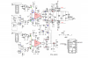
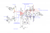
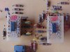
See attachment, not pretty but functional!
The NE592 is a DIP direct replacement, no header required.
I'll post them Monday 25th. OK.
I have been trying to find other sources for the U441 while I was doing nothing and found one on ebay, have a look, is that for 1?
Thats expensive for one!.
If you plan to use the scope for some years, I would buy at least 3 from the web.
**broken link removed**
And whats with the postage, he is in England, not the USA!
Makes the link you sent me look cheap mate, think I will send for one from there.
Anyway thanks again Eric and fingers crossed I will eventually get a working scope
")
Regards..............Al