Continue to Site

Welcome to our site!

Electro Tech is an online community (with over 170,000 members) who enjoy talking about and building electronic circuits, projects and gadgets. To participate you need to register. Registration is free. Click here to register now.

  • Welcome to our site! Electro Tech is an online community (with over 170,000 members) who enjoy talking about and building electronic circuits, projects and gadgets. To participate you need to register. Registration is free. Click here to register now.

Anyone near Rotherham who could test my Scope?

Status
Not open for further replies.
Hi Al,
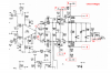
They appear to be Y amp push/pull drivers. If the traces are off the screen, its likely one pair is driving hard and the other is not, thats why there is a tempr difference.

I have been looking at the circuit diagram, if you need more 'input' let me know.:)

Can you still get a trace when you press the 'locate pb'.?

Hi Eric,

Yes I can get a trace by using locate.

Do you think the problem with the Y amp would be the transistors themselves or something connected to them? Should I assume they are iffy and replace the pair?

And by all means Eric carry on with the Input, I can't get enough advice mate, at the moment everything seems to be a problem that is hiding another one!

Do you fancy getting a scope through your letterbox? ;)

Regaards...............Al
 
hi Al,

Look at the attached image.
Measure and write on the dwg the voltages you measure at these points and then repost the dwg.

Before you start that:
Set the X and Y shift pots to their centres of rotation.
Also the same for the brightness and focus.
Set the Sync to internal 'auto'
Set the channels to 'chop'
Channel invert OFF
X time base to a mSec rate ie: 10mS/div
Y amps to 5V dc /div

OK.?
 

Attachments

  • Image2.png
    Image2.png
    285.2 KB · Views: 212
Last edited:
Voltages

Hi Eric,

I did my best to get the readings you wanted, but it is very difficult to follow the diagram to the board as there are no silkscreen prints on it so some of the readings are from the resistor you wanted but I could not discriminate which end was which, in these cases I have drawn the layout and measured both ends.

Here are your values of the numbers you asked for.

1 5v2
2 5v5
3 15v
4 15v
5 15v
6 measured on R182 107v or 35v
7 measured on R186 180v or 170v
8 measured on R181 107v or 180v
9 measured on R184 160v or 170
10 measured on R191 5v7 or 14v9
10a measured on R192 14v9 both ends

The drawing below shows the board from above as does the board picture in the manual, so you can see which end the relevant voltages are present at.

Hope you can understand my less than perfect method of doing this but its the only thing I could come up with.

Edit: BTW it is the large resistors I measured (R181 & R182) that are getting hot, (R184 & R186) beside them and identical packages are still cool!


Thanks again Eric.................Al
 
Last edited:
Here are your values of the numbers you asked for.

these are OK.
1 5v2
2 5v5
3 15v
4 15v
5 15v
---------------------------------------------------

6 measured on R182 107v or 35v
7 measured on R186 180v or 170v
These two are supposed to be the same.! close to +200V


8 measured on R181 107v or 180v
9 measured on R184 160v or 170

these are the Y plate voltages and should be the same for the trace to be central in the Y axis.

10 measured on R191 5v7 or 14v9
10a measured on R192 14v9 both ends

Al

Al,
I dont follow why you have given, for example 107v or 35v, whats that OR mean.?
 
hi Al,
Sorry about that, managed to see what you are doing with the OR.

It looks like TR256/7 could be sick.

A couple more voltage checks, voltage required for both ends of R178 and R179.

and R166 and R167.


OK.
 
Last edited:
hi Al,
Sorry about that, managed to see what you are doing with the OR.

It looks like TR256/7 could be sick.

A couple more voltage checks, voltage required for both ends of R178 and R179.

and R166 and R167.


OK.

Hi Eric,

R167 has 4v4 o both sides
R166 has 3v4 on left and 0v on right
R179 has 6v4 both ends
R178 has 10v9 leftt and 11v on right.

Hope this is ok mate.

Regards....................Al
 
Hi Eric,

R167 has 4v4 o both sides
R166 has 3v4 on left and 0v on right
R179 has 6v4 both ends
R178 has 10v9 leftt and 11v on right.

Regards....................Al

hi Al,
That R166 right shouldnt be 0V.
Look at the attached dwg, the RED line should not be at 0v, its throwing the Y plate amps right out of balance. Thats why the trace is off the screen.

Look at the BLUE boxes. Lift one end of the following components out of the pcb.
C253/R266 and C254/R267. that will isolate the top Y push/pull amplfier from the bottom Y amp.

After you have done that you may get a trace, if you adjust the Y shift.
Repeat all the voltage checks 1 thru 10 and the R166/R167 voltages.

Ideally you want to finish up with the 9/10 Y plates at the same voltage.

Lets know what you find.:)

EDIT:
If that dosnt fix the problem, then check R171/R173. if either of these is open circuit then that voltage on R166 will be 0V.
TR253 could be base to emitter short circuit.

I know its a pain, but I cant see over your shoulder, these are the tests I would do myself..

EDIT2:
As a quick check, measure R171 [1K5] if thats o/c the base of TR253 would be 0V.

These edits are as I keep analysing the dwg, its fuzzy.
 

Attachments

  • scope1.png
    scope1.png
    235 KB · Views: 185
Last edited:
Scope Update

Afternoon Eric,

Right, I found C253 and R266. Do I remove one end of each?

Found R267 but cannot find C254 at all! I think it may be the cap directly above R267 but cannot read the number on the drawing. Hadn't they invented SilkScreening when my scope was made? ;)

Anyway just have a glance and see if you agree.

BTW I re-checked R166 and there is definately 0v on one side ( just thought maybe the probe had hit a bad bit ).

Thanks Eric............Al
 
Forgot to mention, the drawing shows 10 ICs and the scope has 14! :confused:


hi Al,

Try these edits from my last post.

EDIT:
If that dosnt fix the problem, then check R171/R173. if either of these is open circuit then that voltage on R166 will be 0V.
TR253 could be base to emitter short circuit.

I know its a pain, but I cant see over your shoulder, these are the tests I would do myself..

EDIT2:
As a quick check, measure R171 [1K5] if thats o/c the base of TR253 would be 0V.
 
Hi Eric,

Removed C253/R266 and C254/R267 still no trace :(

Checked R171 and R173 and both are within tolerances.

Baffled, maybe I should just get another scope?

I was looking on ebay and found one going cheap that has a small problem ( he says smoothing) annnd wondered if it would be better than mine, at least it can display a sine wave even in its presennt condition.

**broken link removed**

What do you think Eric?

Al

hi Al,
I havn't looked at the eBay link yet.

The fact that transistor base is at 0V indicates the problem is on that small area/line of the circuit,
it should be possible to pin point the problem.

Are you upto testing any more or do you want to move on... :)

EDIT:
Looked at the eBay scope... it needs work,, that EHT hum/fault could be a dodgy crt heater/cathode.
 
Last edited:
Hi Eric,

Yes I am willing to try more tests, I would really like to get it working, I don't usually give up easily, but I am in way over my head here. Without your good self I wouldn't have a clue what to check and would have had to give up before now. :)

I did notice something else last night annd forgot to mention it, one of the CA3046 ICs was in upside down! I assume there is one of these per channel, I refitted them both the same way round, but maybe thats the original cause of one channel dead? I cannot find any reference to their orientation either on the board or drawings so I went with the rest of the vertical ICs on the board!

I just hope that they are not now both upside down and are the only ICs on the board that are! ;)

As I said one of the transistors in one CA3046 is showing as a diode network so I will at least have to order a couple of them, maybe I would be better off just ordering all new ICs and Trannies and swap the lot?

But would that mean everything was uncalibrated?

Sorry to drone on mate, but I have no-one else here I can talk about it with. The missus just calls it my "Silly Scope" and I am wondering if she's right! ;)

Regards................Al
 
hi Al,
OK. I'm game for it if you are.!:)

Keep one end of R266/R267 and C253/C254 disconnected, they are the second Y chann preamps.

Swop over TR253 and TR254 transistors.

Remeasure the voltages on R166 and R167.

Let me know.

I'm having a buy one get one free Sunday, so test away...

EDIT: post the type of transistor for the TR253/4's I cant see them on the dwg.?
 
Last edited:
hi Al,
OK. I'm game for it if you are.!:)

Keep one end of R266/R267 and C253/C254 disconnected, they are the second Y chann preamps.

Swop over TR253 and TR254 transistors.

Eric, do you mean swap the 3046 ICs as TR151 to TR155 are in one IC annd TR251 to TR255 are in the other 3046

let me know........Al

hi,
Even if you buy new ones, you still have to take out the old ones.

By doing a swop it should give an indication if they are faulty or not.

Do you have any old ic sockets you could fit in the ic holes after removal, thats if the pcb isnt souble sided and not using plated thru holes..!

There are differences between the layout and the circuit.
 
Last edited:
Here's the sheet for the transistor arrays containing Tr151-155 annd Tr251-256

Al
 

Attachments

  • ca3046.pdf
    85.1 KB · Views: 218
hi,
Even if you buy new ones, you still have to take out the old ones.

By doing a swop it should give an indication if they are faulty or not.

Do you have any old ic sockets you could fit in the ic holes after removal, thats if the pcb isnt souble sided and not using plated thru holes..!

There are differences between the layout and the circuit.

Hi Eric,

I should mention thata all the ICs are socketed on the board (single sided) and I tried swapping the transistor arrays you said.

Results were R167 5v1 one end - 4v8 other end
R166 3v1 one end - 0v other end

after swap

R167 4v9 one end - 4v6 other end
R166 3v2 one end - 0v other end

So very little difference with swapping mate.

Al
 
hi Al,

Been thru all the photo's.:)

Traced the ic/tracks, marked on these attached images.

These should help you get a fix on the layout.

The CA's are both the same way around.

Let me know how it goes are you going to buy some new CA's
 

Attachments

  • TrackSide1 18.gif
    TrackSide1 18.gif
    216.9 KB · Views: 174
  • CompSide1.gif
    CompSide1.gif
    213.6 KB · Views: 193
Last edited:
Status
Not open for further replies.

Latest threads

New Articles From Microcontroller Tips

Back
Top