Continue to Site

Welcome to our site!

Electro Tech is an online community (with over 170,000 members) who enjoy talking about and building electronic circuits, projects and gadgets. To participate you need to register. Registration is free. Click here to register now.

  • Welcome to our site! Electro Tech is an online community (with over 170,000 members) who enjoy talking about and building electronic circuits, projects and gadgets. To participate you need to register. Registration is free. Click here to register now.

7segment current drain

Status
Not open for further replies.

Mosaic

Well-Known Member
Hi all:
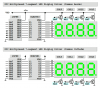
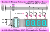
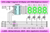
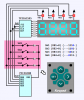
I'm a bit concerned about driving a strobed 4 digit 7segment common cathode from a 16f882 pic.

The Display specs says a 25mA drain, but does that mean PER Digit or altogether?

With a strobe I have to ramp up the current from the PIC to keep the brightness.
I see mentioned in texts to use an 82ohm instead of the usual 330ohm for a single LED, due to the 4x time strobe.

Anyone done this ? What is the real total current pulled from the pic?
 
7 sgement current

UM5624-11 EWRS-R: JAMECO VALUEPRO: Opto & Illumination

That 4 digit spec says max 30mA forward.

But the odd thing is, i check a single digit 7 segment, the current is about the same. Which shouldn't be.
Look at this 1
LA2541-24EWRN: LEDTECH ELECTRONICS: Opto & Illumination, it wants 30mA as well.

The brightness of the units is specified by the mcd (millicandelas) or ucd (microcandelas). For instance a sunlight ready Led is upwards of a 1000 mcd. I can't find ANY 7 segment displays with more than about 13mcd. Those get kinda expensive.

Now the design spec on a 16F882 says 25 mA per pin max for a max of 90mA TOTAL across all the ports. Overall an 800mW dissipation on the chip.

So we have a single 7segment digit with a 30mA need for best Brightness. It's probably 80% bright at 15mA, so we can go with 15mA. Is that 15mA PER Segment, as normal single LEds also use that amount of current? (15mA is just about what u get with a 330 ohm Resistor in line with the LED driven by 5V.)

Then a 7 segment will draw over 100mA each to display a decimal 8. That is in excess of the 16f882 total drive capability. Strobing, I observe, recommends using a higher current drive based on the number of displays to compensate for the timeslicing dimness factor.

If you decrease the 330 ohm to 82 ohm for each line of a 4 digit display, to keep the avg brightness, the current jumps to 60mA per line or 480mA for a fully lit display (decimal 8). This is virtually constant as one digit is always being driven at any moment.

The PIC will die within a few minutes(depending on ambient temps) with that type of load. So I don't think that 'overdriving' the 7 segment when strobing is a good idea, as the PIC is being severely overdriven.

The individual segments over drive needs to be perhaps at least 60mA (15x4) or more when being strobed at a 25% duty cycle (4 digit) for max brightness. If we settle for 50mA, that requires 2 5 transistor arrays (lm3406). Now, the kicker here is if an individual segment is seeing 50mA, then the common cathode is seeing 50 x 8 = 400mA max sink. Therefore the cc stobe lines need a 2n2222 discrete transistor to do that. All that current boils down to delivering < 50% of max current to the the strobed 7 segments.

Given a Transistor hfe of at least 50, that cuts the load on the PIC to 8 mA or less....which makes for a happy PIC.
 
Last edited:
I think I found a couple questions in there that I can answer.

Those display specs' are per segment. If you want the brightness that 15-ma "average" current provides you'll have to bias each segment for approximately 60-ma "peak" current on your 4-digit (25% duty cycle) display. There's no way you can get that much current through a PIC I/O pin.

It's more likely you'll get about 20-ma from each I/O pin which when multiplexed at 1/4th duty cycle will provide about 5-ma "average" current per LED. That's about 160-ma total if all eight segments are lighted in a particular display which is obviously above the total current spec' for the PIC but I think you'll find that it works fine and doesn't burn up the PIC.

Regards, Mike
 

Attachments

  • Mux'd Displays.PNG
    Mux'd Displays.PNG
    60.4 KB · Views: 989
Last edited:
Hmm, That's prob cause the average number of segments lit is about 4-5 which drops it right about where the PIC can handle it. But it won't be bright.

I am doing an automotive app. display, so I need bright.
 
Then use one of the many parallel driver ICs or serial-to-parallel driver or constant current driver ICs.

For example, replace the 74HC595 in the drawing below with a 90-ma per pin TPIC6C595 (or an MIC5821, or an A6821, ad infinitum....).

Regards...
 

Attachments

  • Sparkfun Display Driver.PNG
    Sparkfun Display Driver.PNG
    32.1 KB · Views: 3,381
Mike, I see your name there! That requires an alternative driver interface than the strobe code I built.

Would u have a code sample for that application?

I think that's an awesome solution, once I go C- anode.

Your diagram shows 5 PNP, but I guess the extra is for the colon. Will a regular colon-less display work with 4 pnp?

If so that should just use 5 lines from the PIC, which helps, cause I was 1 pin short overall and was gonna have to do some antics to save a pin.
My current solution used 7 lines to drive the LED plu 2 more via a 74hc139 2-4line decoder, for a total of 9 pins.

Since this is a serial soln, I need to achieve a 60Hz or better overall refresh to eliminate flicker. I may have to use an interrupt to ensure that. Or do some tight timings.

My code cycle atm is about 800us, which is about 6.5ms for a serial 8bit clk. That's 28 ms for a complete 4 digit sweep. Around 35Hz update now.
I figure that might flicker.
 
Last edited:
I don't think I have any example programs that would be useful to you.

I did attach another drawing for common cathode displays. The only serial-to-parallel sourcing driver that I'm aware of is the Micrel MIC5891.

Regards...
 

Attachments

  • 5-pin 4-digit modular.PNG
    5-pin 4-digit modular.PNG
    28.8 KB · Views: 4,750
Last edited:
Would u have a code sample for that application?
I have an example app' for the 5-pin CC drawing but it won't be very useful to you.
I think that's an awesome solution, once I go C- anode.
That's almost a "thank you" so maybe there's hope for you yet (lol).
Your diagram shows 5 PNP, but I guess the extra is for the colon. Will a regular colon-less display work with 4 pnp?
Yes, use four PNP for a "normal" 4-digit CA display or four NPN for a "normal" 4-digit CC display.
If so that should just use 5 lines from the PIC, which helps, cause I was 1 pin short overall and was gonna have to do some antics to save a pin.
Yes, five pins for the display. You can also use a single I/O pin to read up to four switches by driving the switches from the four column select lines. You'll need one signal diode per switch. Switch software is a breeze.
My current solution used 7 lines to drive the LED plu 2 more via a 74hc139 2-4line decoder, for a total of 9 pins.
Since this is a serial soln, I need to achieve a 60Hz or better overall refresh to eliminate flicker. I may have to use an interrupt to ensure that. Or do some tight timings.
Unless there's some compelling reason not to, you should be using interrupts already for the display driver and to sample and debounce switches.
My code cycle atm is about 800us, which is about 6.5ms for a serial 8bit clk. That's 28 ms for a complete 4 digit sweep. Around 35Hz update now.
I figure that might flicker.
A 35-Hz refresh rate is too slow to avoid flicker.

Not sure I follow what you're trying to do at 800-usecs and 6.5-msecs...

Later... Mike
 
Last edited:
I was using a call from the general prog. loop to update the display, which resulted in a display update every 800us or so.
If I keep that method, and use the serial register, an 800 usec clk pulse *8 gives 6.4 ms to update the shift register's parallel out display. Which worx out to abt a 35Hz sweep for a 4 digit display.

Or am I confused again?

I'll use interrupt handling for the tasks u mentioned.

Is it true that the Tpic6c595 being a drain device can only sink and can only be used on a c-anode display device? I see Mouser carries it

Thank you MIKE K8LH, as I have learned a lot today! Didn't know what to look for outside of the reg BCD/7segment decoders. All of which are lo current.
 
You can use 7 buffer transistors to drive the displays. You will need a delay of about 1mS per segment and in this time you can do all your housekeeping.
You will need to drive them at about 50 to 70mA to get good brightness.
 
You will need 4 transistors on the cathodes.
Set up the cirucit. Put the two switches on two input lines and add any other input devices and create a scan sub-routine.
Use a table for the digits 0-9 and the add code to detect the switches.
 
Hi Mosaic,

I threw together an example program in BoostC for the 5 pin 4-digit Common Cathode display.

If you're interested I'll add the few lines of ISR code for sampling and debouncing up to four switches on a single pin (a column driven switch matrix).

Regards, Mike

5-pin-4-digit-modular-png.44730
 

Attachments

  • LED_4_Digit_595.c.txt
    6.4 KB · Views: 330
Thanks Mike,
I'd certainly be interested in the switch code!!

I managed to do an asm coded version of the shift register just from your schematic and the spec. sheets. Wasn't hard at all once i figured out the edge triggering and realised I could use the the clk and serial lines in between display updates cuz the register latches itself.
Crummy thing is that Proteus isn't updating well with that register in the mix. It's only updating half my Digits.
It was workin' until I decided to switch to a CA display and had to place NOT gates to simulate the transistor drivers on the digit anodes.
If I invert the asm code bits I can get it to work. but the NOT gates are a bit 2 much it seems. I needed to setup for a CA display cuz I want to go with the TPIC6C595 register for the 100mA continuous drives. The spec sheet on that says it's DMOS outputs can only sink 100mA otherwise its open collector.
 
Yes, almost all of the serial-to-parallel drivers are sinking drivers or constant current sinking drivers with open collector or open drain outputs. The only serial-to-parallel sourcing driver I have found is the 500-ma Micrel MIC5891 and it's a beauty. It has seperate VDD and VBB pins and so you can easily drive higher voltage displays (white, blue, or large displays with multiple LEDs per segment) with TTL signal levels from the PIC.

The PWM pin is doing triple duty in this K8LH design. You can only re-task the column driver lines for use as <clk> and <ser> pins at the beginning of each column update interrupt when PWM is high (display 'off'). You need to load the driver shift register as quickly as possible after the interrupt and then you write the new column select bit pattern onto the RB4..RB1 column driver lines before PWM goes low again (display 'on'). This means you have to enforce a minimum PWM 'on' time to allow time to load the shift registers.

So, you're leaning toward a common anode design similar to this one (16F88 with PWM output on RB0)?

**broken link removed**
mosaic-1-png.44791


Sample and debounce switches by taking advantage of the column select bit patterns on the RB4..RB1 pins which are '1110' (col 1), '1101' (col 2), '1011' (col 3), or '0111' (col 4). The RB5 switch input pin is using the internal weak pull-up. So you sample one switch during each 1-msec column update interrupt and each switch is sampled in sequence once every four interrupts (once every 4-msecs).

Code:
;
;  select new column after loading the driver shift register
;
isrCol
        movlw   b'00011110'     ;
        iorwf   PORTB,W         ; turn off column select bits
        xorwf   colsel,W        ; active lo column select bit
        movwf   PORTB           ; select new column
Code:
;
;  switch management (sample switch at current selected column)
;
isrSw
        movf    latch,W         ; W = switch state latch
        iorwf   colsel,W        ; set SWn bit to '1' (pressed)
        btfsc   PORTB,5         ; pressed ('0')?  yes, skip, else
        xorwf   colsel,W        ; set SWn bit to '0' (released)
        xorwf   latch,W         ; W = changes, press or release
        xorwf   latch,F         ; update switch state latch
        andwf   latch,W         ; filter out "new release" bits
        skpz                    ; a "new press"? no, skip, else
        bsf     beep,5          ; task a new press beep
        xorwf   flags,F         ; toggle switch flag bits for main
;
Code:
;
;  beep task (32-msec 500-Hz tone @ 1-msec interrupts)
;
isrBeep
        movf    beep,W          ; beep task running?
        bz      isrNext         ; no, branch, else
        movlw   1<<spkr         ; speaker pin mask
        xorwf   PORTB,F         ; toggle speaker pin
        decf    beep,F          ; decrement beep msec counter
Code:
;
;  prep for next column update interrupt
;
isrNext
        incf    colnbr,F        ; bump column number
        bcf     colnbr,2        ; 0..3 inclusive
        clrc                    ;
        rlf     colsel,W        ; advance column select bit
        btfsc   colsel,4        ; last column? no, skip, else
        movlw   b'00000010'     ; reset to first column
        movwf   colsel          ;
        movlw   disp            ; W = &disp[0]
        addwf   colnbr,W        ; add column number, 0..3
        movwf   FSR             ; FSR = &disp[colnbr]
        movf    INDF,W          ; W = disp[colnbr], 0..9
        call    segtable        ; get segment data
        movwf   work            ; SR data for next column
I will work on example C and Assembler code for you.

Regards, Mike
 

Attachments

  • Mosaic 1.PNG
    Mosaic 1.PNG
    17.9 KB · Views: 2,783
Last edited:
Wow! tx Mike, you are an amazing resource! Hopefully, one day, I can help the forum community as well.

gotta study this!

I guess the diodes are to permit s'ware control of the pull up, by floating any low signals?

The micrel chip is about 3x the cost of the TPIC6C chip though, and a bit overkill for regular 7 segment pwr.. Be good for small motors and actuators in robotics though. I will remember it! Saves having to use the ULN2003 type darlingtons with the 74HC595, allowing for more reliable designs.

I found the a6b595 which supplies 50% more pwr than the TPIC6c chip, but open drain as well.

BTW when running 2n3906/04 transistor drivers off the PIC pins, what's the recommended base resistor value? Ic on the Tr is not to be more than 150mA.
 
Well the MIC5891 is a 'sourcing' driver and it is a bit pricey but I suspect it would be well worth the price for a "one off" super clock or scoreboard with those 2 foot high displays that require 12 to 15 volts per segment (LOL).

The signal diodes isolate the switches from each other and from the column select lines. Unlike Colin55's projects, I prefer not to mess up the display when I press push button switches (grin).

That Allegro A6B595 looks a lot like the TPIC6B595. If you look you'll find tons of serial-to-parallel sinking drivers and constant current sinking drivers.

Not sure what to use for the base resistor on your PNP drivers. I usually use P-FET or N-FET drivers with very low Rds(on) spec'.
 
Last edited:
Status
Not open for further replies.

Latest threads

Back
Top