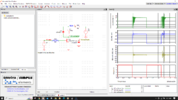
Here is the display section schematic I'm using for a multipurpose clock I'm working on. It might be a bit more clear than the bus nomenclature of the datasheet.
The only weirdness I have here is that the 3rd digit is rotated 180° so I can use the decimal points as a colon for the time. I remap it in hardware so I don't have to mess with it in software.
If you use a multiplexed 4 digit display, the connections are simpler. Eight wires for the segments and 4 for the digit commons.
I'm trying to find the top of my bench so I can get some boards assembled. I'm sure it's down there somewhere
View attachment 140596