Hi
I have 2007 Renault Master in which wipers intermittent function does not work. other functions low and high speed works as well as 3 wipes if you spray watter.
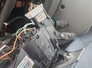
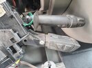
I found some diagrams for this car (look below) and as fas as I understand the wiring of 5wire wiper motor, low and high speed are both pure mechanicaly operated by the wiper stalk. Then there is a intermittend operation and spray wiping that are both controled by the BCM (body control module). In my case spray and 3 wipes works fine but when you put wiper stalk to intermittent function you hear a click from the BCM but wipers does not move.
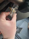
For me it is a "pickle" since I don't think wiper stalk is bad also BCM physicaly looks fine (nothing corroded, nothing burnt), fuses are also all fine and strange thing is that rellay does click.
Also cabin doom light does stay on even if you shut the doors close, and that to is BCM operated (door's switches are fine).
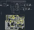
Since both wiper stalk as BCM are expensive (at least 150$) I was thinking to make myself a simple timer rellay for the wiper intermittent function.
Here is the wiring diagrams for the wipers for this car.

212 wiper motor
221 spray pump motor
145 wiper stalk
645 BCM
1016 wiper fuse
ON YT I was looking how a basic 5 wire wiper motor works (wiring of an internal park switch). Everything is understandable, but internal switch on this diagram is different than one provided on the wiring diagram for the car.
Now my understanding is that for a intermittent operation I would need 2 rellays. One providing a 12V pulse to the A1 pin of the wiper motor (low speed), so the wipers would move from its park position and the internal park switch will switch and then I need a 2nd rellay to provide 12V to the A2 pin of the wiper motor. This 2nd rellay has to provide 12V so long that the wiper returns to its park position, then a short delay and everything repeats.
For the input signal for my simple board with 2 rellays i was looking the diagram of the wipper stalk. There are 2 wires going to the BCM (pin VE24 and VE25). First i think is for the spray activation and 2nd should be for the intermittent activation. I guess direct 12V signal is provided on those pins and I will just use voltage divider in my simple board to lead this signal to the PIC mcu.
What are your thought on the matter?
I have 2007 Renault Master in which wipers intermittent function does not work. other functions low and high speed works as well as 3 wipes if you spray watter.
I found some diagrams for this car (look below) and as fas as I understand the wiring of 5wire wiper motor, low and high speed are both pure mechanicaly operated by the wiper stalk. Then there is a intermittend operation and spray wiping that are both controled by the BCM (body control module). In my case spray and 3 wipes works fine but when you put wiper stalk to intermittent function you hear a click from the BCM but wipers does not move.
For me it is a "pickle" since I don't think wiper stalk is bad also BCM physicaly looks fine (nothing corroded, nothing burnt), fuses are also all fine and strange thing is that rellay does click.
Also cabin doom light does stay on even if you shut the doors close, and that to is BCM operated (door's switches are fine).
Since both wiper stalk as BCM are expensive (at least 150$) I was thinking to make myself a simple timer rellay for the wiper intermittent function.
Here is the wiring diagrams for the wipers for this car.

212 wiper motor
221 spray pump motor
145 wiper stalk
645 BCM
1016 wiper fuse
Now my understanding is that for a intermittent operation I would need 2 rellays. One providing a 12V pulse to the A1 pin of the wiper motor (low speed), so the wipers would move from its park position and the internal park switch will switch and then I need a 2nd rellay to provide 12V to the A2 pin of the wiper motor. This 2nd rellay has to provide 12V so long that the wiper returns to its park position, then a short delay and everything repeats.
For the input signal for my simple board with 2 rellays i was looking the diagram of the wipper stalk. There are 2 wires going to the BCM (pin VE24 and VE25). First i think is for the spray activation and 2nd should be for the intermittent activation. I guess direct 12V signal is provided on those pins and I will just use voltage divider in my simple board to lead this signal to the PIC mcu.
What are your thought on the matter?


