Continue to Site

Welcome to our site!

Electro Tech is an online community (with over 170,000 members) who enjoy talking about and building electronic circuits, projects and gadgets. To participate you need to register. Registration is free. Click here to register now.

  • Welcome to our site! Electro Tech is an online community (with over 170,000 members) who enjoy talking about and building electronic circuits, projects and gadgets. To participate you need to register. Registration is free. Click here to register now.

wiper intermittent function

merk

Member
Hi

I have 2007 Renault Master in which wipers intermittent function does not work. other functions low and high speed works as well as 3 wipes if you spray watter.
I found some diagrams for this car (look below) and as fas as I understand the wiring of 5wire wiper motor, low and high speed are both pure mechanicaly operated by the wiper stalk. Then there is a intermittend operation and spray wiping that are both controled by the BCM (body control module). In my case spray and 3 wipes works fine but when you put wiper stalk to intermittent function you hear a click from the BCM but wipers does not move.

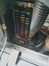
For me it is a "pickle" since I don't think wiper stalk is bad also BCM physicaly looks fine (nothing corroded, nothing burnt), fuses are also all fine and strange thing is that rellay does click.
Also cabin doom light does stay on even if you shut the doors close, and that to is BCM operated (door's switches are fine).

Since both wiper stalk as BCM are expensive (at least 150$) I was thinking to make myself a simple timer rellay for the wiper intermittent function.

Here is the wiring diagrams for the wipers for this car.
ibb.co

212 wiper motor
221 spray pump motor
145 wiper stalk
645 BCM
1016 wiper fuse


ON YT I was looking how a basic 5 wire wiper motor works (wiring of an internal park switch). Everything is understandable, but internal switch on this diagram is different than one provided on the wiring diagram for the car.


Now my understanding is that for a intermittent operation I would need 2 rellays. One providing a 12V pulse to the A1 pin of the wiper motor (low speed), so the wipers would move from its park position and the internal park switch will switch and then I need a 2nd rellay to provide 12V to the A2 pin of the wiper motor. This 2nd rellay has to provide 12V so long that the wiper returns to its park position, then a short delay and everything repeats.

For the input signal for my simple board with 2 rellays i was looking the diagram of the wipper stalk. There are 2 wires going to the BCM (pin VE24 and VE25). First i think is for the spray activation and 2nd should be for the intermittent activation. I guess direct 12V signal is provided on those pins and I will just use voltage divider in my simple board to lead this signal to the PIC mcu.

What are your thought on the matter?
 
So that I can work out how the car is supposed to work, can you tell me what the switch positions do, in order?

Is there a control for the rate of intermittent wipers?

You should only need one relay. You basically just need a relay to fool the system into thinking that you have turned on the wipers. You then activate the relay for about 1/2 second each time you want one wipe.
stalk has intermittent, low and high speed, watter spray as usual on spring.
intermittent and spray function is operated by the rellay in bcm. strange is that 3 wipes of spray works while intermittent doesn' t but i do hear a click. fuses are ok,but otherwise you can see in the diagram there is one fuse.

wiring diagram does not show in detai how stalk internal switches work. one rellay you say? if the stalk to intermittet function switches power to motor park position, then i guess it will be enough to have just one rellay providing a short pulse to the motor low speed
 
Last edited:
i siriously doubt stalk is beeing bad, i thought something is wrong with bcm since other functions relatet to bcm do not work and i think mcu or something of ic are bad ratther than rellays that seems fine. however it is strange that 3 wipes work but intermittent doesnt.
yet rellay does click once
 
Could the intermittent speed control be open circuit - or the wire / a connector pin between that & the BCM be damaged or corroded?

It may be that with no circuit through, the intermittent wipe is active but the time is vastly longer than normal.
 
Is there supposed to be any adjustment available for the intermittent wiper?

There circuit diagram of the switch is quite detailed, and there are some unused connections. Also the windscreen wash motor (labelled 221) has an arrow showing that it can run in either direction, but it is wired in a way that it can only run in one direction. It's quite common to have washer pump that runs in one direction for the front washer and in the other direction for the rear washer. It looks like the vehicle uses components that are also used on a vehicle with a rear wash-wipe.

I think that the circuit shows the internal connections of the switch exactly, and the unused parts can be ignored as they are for a rear wiper.
 
View attachment 140670
If you wire an automotive relay up like this, and activate it for about half a second, the wiper will operate once.
super thx for that i will look it up and try to understand. about the stalk there is no speed switch for the intermittent function, just one speed. connectors on the stalk as on the bcm seems fine. i couldnt remove the stalk as you have to remove the steering wheel for this. bcm also visualy is perfectly fine. i went trough all fuses but will double chech again.
 
Can you monitor the voltage on the wire from pin A2 on the wiper motor, whilst the wipers are operating normally?

It should switch between 0V and 12V (or vice versa) when the blades are in the "park" position.

The drawing shows that signal as only being used by the ECU and no other connections.

I'm wondering if the wiper motor also has a conventional internal park switch connected directly between power and the motor, that is not shown?
If so, a fault in the ECU park switch signal could prevent the intermittent function from working.
(eg. It's waiting for a "parked" indication before starting to time the next sweep delay).

ps. If the column switch diagram is correct and the switch is OK, you should see continuous 12V on switch wire A1 when the column switch is in the intermittent position.


However, I do not trust that diagram - there does not appear to be any direct power feed to the motor, or indication to the ECU that the wipers are on!

Switch A1 & A7 shown reversed, possibly? A1 being the fused power feed and A7 the switched wire to the ECU would make a lot more sense!

If A7 switches on in the intermittent position only, then the diagram is messed up.
 
I'm wondering if the wiper motor also has a conventional internal park switch connected directly between power and the motor, that is not shown?
I don't think that there would be another park signal. The third wire to the wiper motor is to make it run at a higher speed. That is usually done by having a 3rd brush on the motor. The normal speed brushes are at 0° and at 180°. To run at high speed, the 0° brush and the 3rd brush at about 120° are used.

As you said, the A2 wire tells the BCM if the motor is in the parked position. I can't see reason to have a second park switch.

However, the park switch has a +12V and a 0V feed to it. If the park wire was only there to tell the BCM when the wipers are in the park position, there would be no need for a changeover switch. A NO or NC switch could have been used and with small current with a pull-up resistor, and wire AP27 could have been omitted entirely.

I suspect that pins 2 and 4 on the BCM are connected together by the BCM when the wipers are turned of, so that the 12V power comes from the parking switch. When the park position is reached, the the switch changes over and the motor is shorted out so that it stops quickly.
 
This is a possibly more accurate version of the wiring diagram - the 2006- model rather than 2003-2005 model.
The power feed to the lowest switch section now makes sense (to the common rather than to a single position), so hopefully the rest is also OK...

Renault_Master_06_Wipers.jpg
 
This is a possibly more accurate version of the wiring diagram - the 2006- model rather than 2003-2005 model.
The power feed to the lowest switch section now makes sense (to the common rather than to a single position), so hopefully the rest is also OK...

View attachment 140678
That circuit appears to have a variable resistor which is connected when the wiper is in the intermittent position. I guess that would be the adjuster for the intermittent rate, which the OP is says isn't present on his van.
 
This is a possibly more accurate version of the wiring diagram - the 2006- model rather than 2003-2005 model.
The power feed to the lowest switch section now makes sense (to the common rather than to a single position), so hopefully the rest is also OK...

View attachment 140678
Don't know how you found this diagram, I searched the internet and all i could find for free was for 2003.
However I don't know how car's repair manuals works but I will say this is not what is in my van. My van is year 2007, sold in Slovenia, made in France, but if I go step by step.
1st I have no rellay on the fuse&rellay board for the wiper (on this diagram 1040 is a wiper rellay), I also don't here no clicking on the rellay board when wipers are on
2nd I only have 1 intermittent speed, on this diagram there is a variable resistor selector.
3rd wiper stalk here has no direct wiring to the wiper motor, there are only 2 wires going to the BCM (probably each switch has its own resistor)
4th if I remove BCM my wipers still works on low and high speed, so there has to be direct wiring from the stalk to the wiper motor as on the 2003 diagram

I'll say 2003 X70 diagrams are correct for my van.

You previously said to me that there is only one rellay for intermittent function then I predict this same rellay is also used for 3 auto wipes when you spray watter.

Now I am thinking maybe stalk is faulty. Intermittent switch is like 1st gear in gearbox - it is most frequently used as it is first switch on the stalk. Consider this it is logicaly to go bad first.

I just don't know how to test the stalk? First it is hard to acces it (you have to remove steering wheel to acces it), but acess to the BCM is easier.
Once again I do hear rellay click in the BCM after i move stalk to the intermittent position. I guess A1 pin on the stalk seends voltage to the VE24 pin on the BCM and I think that is ok, since rellay clicks. But in order for the wiper motor to move from its park position the stalk should also provide a path for the current to flow to low speed pin on the motor. Maybe here is the problem.

I would like to understand how this stalk internal switches works in order to replicate the stalk intermittent position to test if it really stalk that is the problem.

However the diagram provided (for the 2003 model) is not logic to me. Wiper motor internal swith is not as one on the common wiper motor.
 
3rd wiper stalk here has no direct wiring to the wiper motor, there are only 2 wires going to the BCM (probably each switch has its own resistor)

The '03 diagram has the stalk switch controlling the two main power wires direct to the motor: 14A and 14B

On that diagram, terminals A1 and A7 are shown reversed; A1 is power from the 30A fuse, and for normal low/high speed wipers power is connected straight through from A1 to one or the other of those motor wires.

A7 sends power to the ECU from A1 when in the intermittent position, and A6 connects the motor low speed power through to the ECU when the switch is in either stop (park) or intermittent positions.
Note that the matching 06 Owners manual shows fixed-speed intermittent wipe. The resistor in the switch could be a factory preset?

If your switch really does not have any wires direct to the motor, then the '03 drawing is very! wrong as well!

What is the exact model & engine of the vehicle? The manual set I found all start with NT8xxx IDs? eg. The 06 diagram is from service manual "NT8322"
Can you post a photo of the wiper stalk markings?

(ps. The relay in the '06 diagram is "high speed" only).

Edit - Which version on here does it match??
 
If you want variable rep rate , this requires 2 one shots. The 1st is a short to trigger starting the wiper sequence and the 2nd variable delay with range constraints. If you want that automated by windscreen IR reflections from rain, thats a little more effort.
 
here are the photos of the van, wiper stalk, stalk connector and wire colours as the incabin fuses and rellays. i went trough all the fusses with ohm metter and they are fine, but when i was also measuring the voltage i found out that most of the fuses on the center column do not have any voltage present.

one important thing to mention again. when you move stalk to 1st poition (intermittent) rellay in the bcm clicks but wipers do not move. when you put stalk back to rest position wipers make one revolution and park.
 

Attachments

  • received_1258586598060389.jpeg
    received_1258586598060389.jpeg
    304.6 KB · Views: 175
  • received_537129678541748.jpeg
    received_537129678541748.jpeg
    197.8 KB · Views: 169
  • received_616256286974248.jpeg
    received_616256286974248.jpeg
    244.7 KB · Views: 166
  • received_744392140647721.jpeg
    received_744392140647721.jpeg
    264.2 KB · Views: 170
  • received_724987379319030.jpeg
    received_724987379319030.jpeg
    241.4 KB · Views: 166
  • received_512585971052667.jpeg
    received_512585971052667.jpeg
    222.2 KB · Views: 186
  • received_199219812760690.jpeg
    received_199219812760690.jpeg
    306.8 KB · Views: 171
  • received_3398296273832514.jpeg
    received_3398296273832514.jpeg
    45 KB · Views: 166
  • received_1716849042069592.jpeg
    received_1716849042069592.jpeg
    44.7 KB · Views: 161

New Articles From Microcontroller Tips

Back
Top