Continue to Site

Welcome to our site!

Electro Tech is an online community (with over 170,000 members) who enjoy talking about and building electronic circuits, projects and gadgets. To participate you need to register. Registration is free. Click here to register now.

  • Welcome to our site! Electro Tech is an online community (with over 170,000 members) who enjoy talking about and building electronic circuits, projects and gadgets. To participate you need to register. Registration is free. Click here to register now.

Wind energy to electric energy

Status
Not open for further replies.
williB said:
does it seem right that with 6V peak to peak pre rectified volts..
that i am only getting about 3.3V no load rectified volts ??

Yes, peak to peak is double the value of peak, so when you rectify it the zero to peak value will only be 3 volts or so.
 
ok after i put just two magnets on a strip of steel..
and passed them over "just one" of the thinner wire armatures ..
i got 2V peak to peak !!!!
that is amazing !!
imagine how much voltage i could get with a magnet on either side of the coil.. like the double rotors of earlier discussion..
that is , an armature set , sandwiched between two rotors with magnets attracting each other..
 
this is my current test fixture..
i need a lathe damnit! lol
the smaller silvery magnets are much more powerful than the larger magnets..
With the eight home depot magnets still in place and the eight new Neodymium magnets i just got 10V p-p :D
 

Attachments

  • magnet_new__.jpg
    magnet_new__.jpg
    16.8 KB · Views: 1,015
  • magnet_rotor.jpg
    magnet_rotor.jpg
    18.1 KB · Views: 1,178
i am pondering the idea of putting some iron core/ laminates in the center each winding , anyone have any thoughts . would it be a good or bad idea ? and why ?
would it be a waste of time or could i get more voltage out of it if i used laminates or would they just interfere with the simplicity of the generator ?
 

Attachments

  • armature4_814.jpg
    armature4_814.jpg
    16.6 KB · Views: 1,000
Eh WilliB,
I'm sure on windstuffnow you can but 10" disc's off them cheap about 10 bucks I think. I'm sure Ed could supply you with a disc you need just take a look.


Cheers Bryan1 :D
 
i'm at the point in the design stage where i need more info..
i need to know how much torque the savonios wind generator can produce ..
i am thinking of one the size of a 5 gal bucket..
i need to know if a 3 to 2 gear ratio is to much or if a 1 to 1 is best..
i found a source for sprockets and chains..
https://sdp-si.com/eStore/Direct.asp?CP=Index.htm
i am going to use a chain because
1) low losses involved in transferring power
2) so i dont have to connect the savonius wind generator directly to the top of the rotor..
just thinking out loud so to speak..
 
i found a 8 inch plywood saw blade at home depot to use for the rotor ( just gotta grind off the teeth..) $6.95
and i found a 2 gal bucket for the savonius part at the dollar store..
 
another update on the output of the Permenant Magnet Generator project ::
i am now getting 15 V p-p with 7 armatures and 16 mannets spaced as above .. the plan is to use 8 armatures .. Each armature has a resistance of about 0.9 to 1.0 ohms..
the sine wave is sweet , BTW .. the faster it goes the more voltage you get from it..
This is all spinning the rotor by hand , somewhere around 150 RPMs ..
 
am i talking to myself here ?
anyway

the first pic is the new rotor built on an 8 inch saw blade.. with the https://www.windstuffnow.com/ magnets mounted sort of where they will end up..
the second pic is the savonius wind generator part with a cd on top for size reference..it is built with a 2 gal bucket
i have another disk like the base to put on top courtesy of home depot , it came from a used spool from the electrical wire section ..
as for bearings , i have two that i can use , i am going to ues fiberglass resin to secure them in place..
 

Attachments

  • wind_gen_side.jpg
    wind_gen_side.jpg
    11.9 KB · Views: 892
  • wind_generator.jpg
    wind_generator.jpg
    16.5 KB · Views: 910
  • 1_rotor.jpg
    1_rotor.jpg
    9.7 KB · Views: 959
Oh well :( 
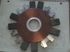
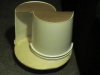
the plywood disks arent cutting it.. too heavy
too much mass to react fast enough to a gust of wind..
i'm thinking 1/8" plexyglass would work much better..
 
EDIT : just the savonius part turns with the wind from the pc fans i havnt hooked the generator to it yet
i think that i will put the generater underneath after all..
 
I havnt mentioned it yet but i plan on using a PIC controller to monitor the rotation speed of the generator and compare it to an Anemometer..
If the generator slows down compared to the speed of the wind meter then i could disconnect the load till it speeds up again..
 
williB said:
this is my current test fixture..
i need a lathe damnit! lol
the smaller silvery magnets are much more powerful than the larger magnets..
With the eight home depot magnets still in place and the eight new Neodymium magnets i just got 10V p-p :D

"Still living...not dead yet" :lol: Still reading along, mate. Great work.

You can make a lathe from a hand drill, but I cannot find the link just yet.

*********
found a One for a CNC machine
**broken link removed**

foam lathe
https://www.dansworkshop.com/Hot wire foam cutting.shtml
 
thanks for the links ..
I think that i am going to use one of my 5 1/4 hard drive spindle /motor assemblies for the lathe , i allready used it to fabricate the plexi glass , that and a dremmel , worked pretty well..
the nice thing about using the assembly is that you can bolt it down with three screws , the holes are allready there..
one of hard drive (assemblies) also had a linear slide which could be used as a tool holder with some modifications..
 
another update ::
I just mounted ONE armature , and when i spin it fast , I get 4 Volts p-p !! .. from one armature !!
that works out to 32 V single phase p-p ..Eight armatures at 4 V each.. i wonder if it will turn out that way..
i have the spindle mounted on a very flat board of mahagany and the armature mounted to the board .. the spacing between the magnets and the armatures is less than 0.010 of an inch , which i believe is critical to get maximum voltage ..
 
that white paper between the base and everything else is a layout of where to put the armatures..
as you can see i am only using two pieces of threaded rod to mount the armatures that seems for now to be enough..
 

Attachments

  • test_setup.jpg
    test_setup.jpg
    32.4 KB · Views: 1,053
neat waveform huh ?
this is from one armature and two magnets , and a light spin . and 1 V/ Div
its amazing how This turns into a sinusoidal wave with evenly spaced magnets and armatures..
the first negetive going pulse is when the armature encounters the first magnet..
the positive spike is when the armature encounters both magnets ..
the second negetive going pulse is when the second magnet leaves the armature..
when you spin it the other way the waveform is inverted.
 

Attachments

  • one_armature_output.jpg
    one_armature_output.jpg
    9.3 KB · Views: 1,039
Status
Not open for further replies.

Latest threads

New Articles From Microcontroller Tips

Back
Top