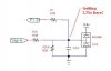
I am trying to get a the input protection circuit right for protecting I/Os from outside signals (which are up to 30v). For this, I am trying to use BAV99, that is connected to ground on the one side and Vcc to the other (Vcc being 3.3v). But when I connect the external voltage, I get 3.75 at the BAV99 junction. Now I (sort of) understand that this is Vcc + the drop on the diode. But what I don't understand is, given this this is a standard way of protection, how can it ever be proper if it is always Vcc + 0.4? That will always push it very close to the micro controller's limits? (my circuit is attached)
Continue to Site