Continue to Site

Welcome to our site!

Electro Tech is an online community (with over 170,000 members) who enjoy talking about and building electronic circuits, projects and gadgets. To participate you need to register. Registration is free. Click here to register now.

  • Welcome to our site! Electro Tech is an online community (with over 170,000 members) who enjoy talking about and building electronic circuits, projects and gadgets. To participate you need to register. Registration is free. Click here to register now.

Will micro be damaged by negative rail opamp?

Flyback

Well-Known Member
Hi,
Will the micro be damaged by the (non series resistor protected) opamp input?
LTspice and jpeg attached.
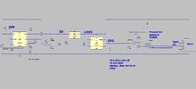
The micro has a -3v3 rail, and a 20V rail.
Micro has rail +3v3 to 0V.
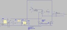
Its a TL084C opamp.
What would be the worst circumstance for the micro?
The opamp output current is clamped to some 26mA, as you know....maybe micro can withstand a short blast at 26mA?

TL084C opamp

STM32F103V micro (100pin)

The opamp goes into pin 35 of the micro which is labelled as an Analog input. ("PB0/ ADC_IN8 /T3_C3")
 

Attachments

  • Opamp to micro___Negative rail 1.jpg
    Opamp to micro___Negative rail 1.jpg
    153 KB · Views: 107
  • opamp neg3.asc
    5.5 KB · Views: 98
A SMT resistor cost is fractions of a penny. And if you employ a 0201 or even a 0402 package, the required board real state is close to negligible.
Ultra cheap insurance. Use it.
 
D2, D3 input protection diodes have a max current rating. Read the data sheet. Or some how (resistor) limit the current. I would pretend the op-amp output goes from rail to rail and pick a resistor based on that.
 
There is a school of thought that the opamp is a buffer...and that since its non-inv pin is never <0V, then neither should be the output.....though is there something with offset voltages of certain batches?...that when inv and non-inv are both 0V......it could be that non-inv "looks like" it is less than 0V?...so opamp output goes to negative rail?
 
Do you really need an op-amp buffer? What is providing the PWM signal?
 
The attached explains it better...yes we need the buffer....its too high Z divider to send several cm's across the board back to the micro.

the attached sim is nearer what we are doing with the circuit........in the attached LTspice sim, after a few ms, the 20V rail goes down as the product is switched OFF......but the neg_3V3 rail stays about neg_3v3...its at this point where the big injection of current goes through the ADC pin 's ESD diodes....because the opamp output goes negative.

I think this is the danger point of the circuit...would you agree?
 

Attachments

  • opamp neg5.asc
    9.3 KB · Views: 93
  • opamp neg 5.jpg
    opamp neg 5.jpg
    145.7 KB · Views: 92
A SMT resistor cost is fractions of a penny. And if you employ a 0201 or even a 0402 package, the required board real state is close to negligible.
Ultra cheap insurance. Use it.
thanks
[i must confess, i never encountered this before, as i always put a series resistor there...but this board has already been done and there's no room for the eight series resistors that would need adding......the whole board would have to be totally ripped up and started over. (a consultancy actually sent us this as they are overloaded at the mo)]
Modify message
 
 
Last edited:
and the statement
The opamp output current is clamped to some 26mA
isn't accurate. The datasheet lists 26mA as the TYPICAL output short-circuit current... it's not the max nor is it "clamped"

Even if it doesn't blow anything up usually injecting a negative voltage causes all sorts of problems with any analog circuitry inside the uC. I wouldn't rely on just limiting the current with a resistor.
 
and the statement

isn't accurate. The datasheet lists 26mA as the TYPICAL output short-circuit current... it's not the max nor is it "clamped"

Even if it doesn't blow anything up usually injecting a negative voltage causes all sorts of problems with any analog circuitry inside the uC. I wouldn't rely on just limiting the current with a resistor.

There are internal protection diodes on a PIC, so it simply needs a suitable series resistor to limit the current.
 

Latest threads

New Articles From Microcontroller Tips

Back
Top