Hello,
I'm sorry, it connects (or rather should connect) to a virtual voltage source (which is almost like a virtual ground), which is seen (or should be seen) at the inverting terminal.
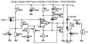
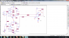
If the lower 1k went to ground then the non inverting terminal would get a voltage. Right now you effectively have a current source powering the lower 1k resistor in series with a 500k resistor. So even the smallest current could develop a very high voltage.
If you look back at the original circuit (with the two current mirrors only) you'll see the 1k connecting to the inverting terminal which acts as a virtual ground so the current mirrors can create a voltage (or just a current through the 1k if you look at it that way). With the new circuit it goes to (or should go to) a virtual voltage source.
To make a long story short, if the output of the lower two current mirrors went to a resistor of 1k then they would create a current that would show up as a voltage across the resistor and that would be driving the non inverting terminal. If you dont understand why, then maybe you can explain why you chose to use a 500k resistor on the non inverting terminal to ground.
I'm sorry, it connects (or rather should connect) to a virtual voltage source (which is almost like a virtual ground), which is seen (or should be seen) at the inverting terminal.
If the lower 1k went to ground then the non inverting terminal would get a voltage. Right now you effectively have a current source powering the lower 1k resistor in series with a 500k resistor. So even the smallest current could develop a very high voltage.
If you look back at the original circuit (with the two current mirrors only) you'll see the 1k connecting to the inverting terminal which acts as a virtual ground so the current mirrors can create a voltage (or just a current through the 1k if you look at it that way). With the new circuit it goes to (or should go to) a virtual voltage source.
To make a long story short, if the output of the lower two current mirrors went to a resistor of 1k then they would create a current that would show up as a voltage across the resistor and that would be driving the non inverting terminal. If you dont understand why, then maybe you can explain why you chose to use a 500k resistor on the non inverting terminal to ground.