Continue to Site

Welcome to our site!

Electro Tech is an online community (with over 170,000 members) who enjoy talking about and building electronic circuits, projects and gadgets. To participate you need to register. Registration is free. Click here to register now.

  • Welcome to our site! Electro Tech is an online community (with over 170,000 members) who enjoy talking about and building electronic circuits, projects and gadgets. To participate you need to register. Registration is free. Click here to register now.

Why Opamp with potentiometer?

Status
Not open for further replies.
Hi,

Yes but one is specified as -15v rather than just plain old 15v. That also makes one of them negative.
 
Hello again,

We would all like to know why the current mirrors are being used. It could be as simple as extending the usable output voltage range (because it will do that), but i dont want to guess at this point what the original designer had in mind.

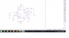
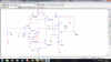
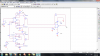
To clarify again, when i say the first stage i mean both the first op amp on the left and the (now) four transistors. The output of the first stage then appears across R1 because the right side of R1 is at virtual ground, and virtual ground is very close to zero volts.

As i am sure you know, a current mirror takes an input current of some level and outputs a current at that same level in the output branch. The two current mirrors are connected to the supply lines of the left op amp, so they mirror the positive supply current and negative supply current. Since their output junctions are connected together and to R1 that has the other end connected to virtual ground, the current through R1 is the difference in currents that the op amp draws from the positive and negative supply rails. So if the op amp draws 1.1ma from the positive supply rail and the op amp draws 1ma from the negative supply rail then the current through R1 is the difference 1.1ma-1.0ma which equals 100ua. So the current through R1 is:
iR1=Ip-In
where Ip is the positive rail current and In is the negative supply rail current.

Now when the left op amp has zero input, there is zero output (assuming zero offset for now). Zero output voltage produced zero current in R2, so the positive rail current is the same as the negative supply rail current which would be the quiescent current draw of the op amp. If this was 1ma then that would appear in both rails, so iR1=0 also.

When a positive voltage is applied to the left op amp, the output goes higher by the same amount. So for 1v input the output of the left op amp goes to 1v also. This produces a current equal to:
Iout1=Vout1/R2

This current must come from the positive rail, so now the positive rail current is higher than the negative rail current so we get a net output current from the two current mirrors of:
iR1=Ip-In

and since the current in R2 is now 1/10000=100ua we have iR1=100ua also.

We could now state the transconductance of the first stage, which would be:
gm=100ua/1v=0.0001/1=100uS

but it's also a simple matter to state the voltage output of the first stage because the current iR1 produces a voltage Vout1=iR1*R1 so the voltage is:
Vout1=Vin/R2*R1

so the voltage gain of the first stage is:
Vout1/Vin=R1/R2

The second stage (the right side op amp) has a gain R3/R1, so the overall voltage gain of the whole circuit is:
Av=(R1/R2)*(R3/R1)=R3/R2

We might be able to call the two current mirrors used that way a "Norton Amplifier" because it works on the input difference of two currents rather than the difference of two voltages, for what it is worth. More strictly speaking though we could probably call the two current mirrors combined with the output op amp stage a Norton Amplifier because it takes the difference of two input currents and amplifies that difference into a voltage output. We could look into this more.


Thank you so much for your help, I really appreciate it. I have no clue why the current mirror is used, either. As you said it doesn't play an important role on increasing the
gain. besides I don't understand what Jony said!
 
When I try to regulate offset voltage of op amp, the output voltage starts oscillating.
I want to see this kind of oscillation in pspice simulation but I have two problems,
First, I don't know how can i find an op amp with offset pins because almost all of these
sort of ports are unmodeled. Second, I don't know how to apply noise to the circuit in
pspice to see the oscillation. I ran into a big problem with circuit. Please Help :-((
 
When I try to regulate offset voltage of op amp, the output voltage starts oscillating.
If you built the circuit on a solderless breadboard then the capacitance between the many rows of contacts and the many long jumper wires all over the place might cause oscillation.

The positive and negative supplies need a bypass capacitor very close to pin 4 and pin 11 of the opamp and close to ground to prevent oscillation.
The unused opamps should be properly disabled to prevent them from oscillating.


You mean I should add capacitor to negative and positive supplies of both 2 op amps?
 

Attachments

  • Untitled.png
    Untitled.png
    72.7 KB · Views: 174
But the negative battery is shown as a positive battery.

Hi again,

Yes but that should not matter for the simulation.

Either of these...

For the positive supply:
1. Positive battery with positive terminal to positive supply pin of IC
2. Negative battery with negative terminal to positive supply pin of IC

and for the negative supply:
3. Positive battery with negative terminal to supply pin of IC
4. Negative battery with positive terminal to supply pin of IC

He happens to be using choices #1 and #4 which should be ok.

I've included a drawing with the related terminals circled in red for negative and green for positive.
 

Attachments

  • Amplifier_Vcc-1.gif
    Amplifier_Vcc-1.gif
    7.9 KB · Views: 198
You mean I should add capacitor to negative and positive supplies of both 2 op amps?
Sorry, I forgot that the power supply pins of the opamp have current mirrors that also might make them oscillate.
Try adding a 0.1uF ceramic capacitor to ground at pin 4 and pin 11, but then the current mirrors might oscillate.

Maybe you should get rid of the current mirrors and make a normal opamp circuit.
 
When I try to regulate offset voltage of op amp, the output voltage starts oscillating.
I want to see this kind of oscillation in pspice simulation but I have two problems,
First, I don't know how can i find an op amp with offset pins because almost all of these
sort of ports are unmodeled. Second, I don't know how to apply noise to the circuit in
pspice to see the oscillation. I ran into a big problem with circuit. Please Help :-((

Hi,

What is the frequency of oscillation? That could tell us what is causing this.

An interesting trial would be to connect the output of the current mirror to the inverting terminal rather than the output of the op amp.

Also, how do you have your offset null pot connected? This op amp seems to require both 'ends' of the pot to go to the negative supply line.
 
Hi,

An interesting trial would be to connect the output of the current mirror to the inverting terminal rather than the output of the op amp.

what do you mean? in this circuit the output of current mirror connects to a resisitor,
this resisitor goes to either output of op amp or the inverting input. I don't get what you
meant :-((
 
Hi,

I'm sorry, i worded that wrong. I meant this:

An interesting trial would be to connect the output of the current mirror to the inverting terminal of the first op amp, rather than having the output of the first op amp connect to the inverting terminal. The resistor 10k would still go on the output of the first op amp, but the feedback would now come from the output of the current mirror rather than the output of the op amp.

Just in case that is still not clear, another way of saying this is to do this:
Disconnect the output of the first op amp from the inverting terminal but not from the 10k resistor. That leaves then inverting terminal open.
Next connect the output of the current mirror to the inverting terminal, then try running it up and see what happens. Leave the output of the current mirror connected to the 1k too and the second op amp can stay in place also. It's just that now the feedback for the first op amp comes from the output of the current mirror rather than the output of the first op amp. That's the only difference.

This is just something to try to see how it works that way.

To simulate this more exactly and maybe get more real world results with either circuit, build up the op amp circuit itself using the data sheet internal diagram for the op amp which uses transistors. You can use very low power signal type transistors for the parts they show in the diagram.


I would be grateful if you check the image I 'm not sure you meant this circuit or not. I ran this in pspice and got (-13v) as output voltage. In previous circuit I got 1.04 V
I don't get why is there such a difference?
 

Attachments

  • Untitled 1.png
    Untitled 1.png
    132.4 KB · Views: 147
  • Untitled1.png
    Untitled1.png
    126.3 KB · Views: 158
Last edited:
Hi,

That looks right but it looks like it is causing a latch up so something else would have to be added to prevent that. The idea was to feed back the output of the current mirror in order to ensure it was corrected, if needed. We'd have to investigate this more to see why it latches up.

In the mean time, are you saying that you get 1.04v out before this change? So it doesnt oscillate anymore then?

I simulated both of these circuits in Pspice and These results (1.04 and -13) have been got from simulation. In real world when I assemble on soldress breadboard and
want to regulate the offset voltage after some time it starts oscillating! :-(
I still don't know what's the reason of oscillating.
 
Would anyone please tell me why I get zero volt from this circuit in Pspice when one of input is (1v) and the other is (-1v)?!
 

Attachments

  • Untitled.png
    Untitled.png
    133.8 KB · Views: 162
Frequency of oscillation is 2Mhz, frequency is high for this circuit I don't know what should I do to reduce it :-((

Hi,

How high is the amplitude at the output of the first op amp when it oscillates?

One possibility is that when the op amp draws current from the power supply the current draws the voltage down and then the op amp draws a little less current then it goes back up then the current goes back up, etc. Look at the power supply rails with a scope maybe with AC coupling to see the changes.

In your new circuit, dont you have to have one end of that 1k resistor (on the output of the lower current mirror) connected to ground? Then the output of the current mirror would also connect to the non inverting terminal of the right side op amp.
 
In your new circuit, dont you have to have one end of that 1k resistor (on the output of the lower current mirror) connected to ground? Then the output of the current mirror would also connect to the non inverting terminal of the right side op amp.

Sorry I don't get what you said. due to the symmetry, differential voltage should be zero I think one thing is wrong because by applying (-1v) to one of inputs I get zero volt
at the output.
 
Hi,

In the lower section, if you apply a voltage the output current mirrors generate a current, and that current should run through a resistance so that it produces a voltage. In the top circuit this is no problem because the 1k goes to a virtual ground, but in the lower section the 1k goes to a very high impedance of 500k. That might not work. Remember the current mirrors generate a CURRENT not a VOLTAGE by their nature.

First of all would you please tell me why 1k in the upper section goes to virtual ground?
 
Status
Not open for further replies.

Latest threads

New Articles From Microcontroller Tips

Back
Top