Continue to Site

Welcome to our site!

Electro Tech is an online community (with over 170,000 members) who enjoy talking about and building electronic circuits, projects and gadgets. To participate you need to register. Registration is free. Click here to register now.

  • Welcome to our site! Electro Tech is an online community (with over 170,000 members) who enjoy talking about and building electronic circuits, projects and gadgets. To participate you need to register. Registration is free. Click here to register now.

Controlling servo motor wirelessly with a potentiometer

Markus1234

New Member
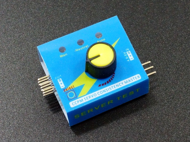
Hello, I have a project at school which requires me to be able to control a servo motor wirelessly using some form of a potentiometer. I made a prototype using the fs1000a sender and receiver, with a 9V battery, voltage converter, servo tester and the transmitter on one side, and a 9V battery, voltage converter, capacitor, receiver and the servo motor on the other side.

Using this setup with both original and extended antennas yielded poor results. The range didn’t seem to be more than 40-50cm, and the servo was shaking and spinning mindlessly.

Am I doing who’s wrong? How would you have solved this?
Thanks in advance, Markus :)
 
The servo uses the on/off duty cycle of a 50Hz square wave signal typically used to set the position of the servo.

How are you encoding the duty cycle information into the RF carrier wave?
Amplitude shift keying
Modulation shift keying
Phase shift keying
Frequency shift keying.
are some common ways of sending data to a device.

The chatter suggests an unclear implementation of a communication protocol on the sending and/or receiving side (or, no clearly defined protocol was used in the first place).

Give some more details of your project.
 
Thank you for responding!
I assumed using one of these in the transmitting end would be enough?
On the website above, 50hz was mentioned, but I couldn’t find any information about the “duty cycle information”. Could this be the problem

It is a really “dumbed down” project, and I try to use as few/small parts as possible. I saw some YouTube videos using an Arduino computer, but because of the size, I try to avoid using one.
Regards, Markus
 
Hello, I have a project at school which requires me to be able to control a servo motor wirelessly using some form of a potentiometer. I made a prototype using the fs1000a sender and receiver, with a 9V battery, voltage converter, servo tester and the transmitter on one side, and a 9V battery, voltage converter, capacitor, receiver and the servo motor on the other side.

Using this setup with both original and extended antennas yielded poor results. The range didn’t seem to be more than 40-50cm, and the servo was shaking and spinning mindlessly.

Am I doing who’s wrong? How would you have solved this?
Thanks in advance, Markus :)
Well personally, I've had no luck whatsoever using the FS1000A modules, which I've bought from various sources at various times - I use PIC's, but in desperation I've tried Arduino as well, using the various libraries and examples available, and none of those worked.

I even tried buying some slightly more expensive superhet radio modules, they didn't work either :D

I've had digital scopes on the transmit and receive modules, and regardless of range or aerial sizes, the received data stream bears little resemblance to the transmitted one.
 
Its a shame, but on this forum somewhere, we have loads of lil circuits you need..

When it was updated loads of tutorials and examples etc... all went randomly in a pletherer of lost pages.. They are still there but hard to find... I myself posted hundreds of examples and help files but even I have trouble finding them now.

I'm sure member Alec_t made a PWM circuit for testing stuff
 
Last edited:
Hello,

If I was going to do this I would make the receiver somewhat independent of the transmitter. That is, the receiver would receive a code that tells it what setting to use, and it would use that setting to drive the servo and continue to use that setting until the next code came in. Maybe have a fail-safe time delay to turn off if no signal is received.

This should work better than trying to control the duty cycle straight from the transmitter to the receiver to the servo, as comm channels always have a risk of dropping out momentarily due to RF interference.
 
I would use a pair of ESP32. One in "Station + Access Point" mode as a server with the potentiometer - use the onboard ADC to sense the potentiometer position. Use a simple html web interface or UDP feed to make the pot position data available.

On the receive side, set up as a client that grabs the value from the server and bit-bang the 50Hz PWM to an output pin that positions the servo.

If the servo needs a 6v power supply, simply use a few diodes to drop the voltage to 3.0 to 3.6v for the ESP32. You'll have about 10m range and little fear of interference .
Sounds promising, would I need anything else besides a potentiometer, a servo motor, the two boards and power supplies?
 
Sounds promising, would I need anything else besides a potentiometer, a servo motor, the two boards and power supplies?
The software know-how to modify the example code for Server and example code for client. And a PC to write and transfer the code to the ESP32.
 
Sounds achievable, I will order a couple of boards and hope for the best!
Thank you!
Order the versions with usb connector - makes life easier.
 
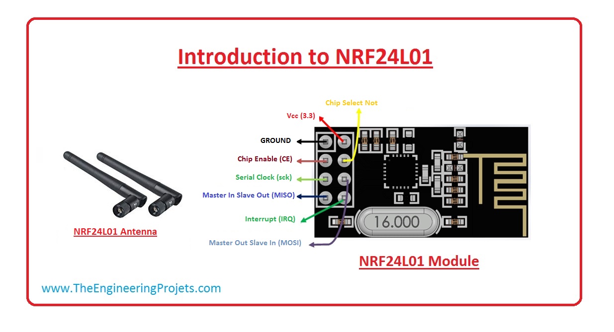
If you find fs1000a unreliable you can use NRF24L01 instead. NRF24L01 is basically a wireless transceiver, which is used to send and receive data by using radio waves. It is a single chip transceiver module.


Latest threads

New Articles From Microcontroller Tips

Back
Top