Continue to Site

Welcome to our site!

Electro Tech is an online community (with over 170,000 members) who enjoy talking about and building electronic circuits, projects and gadgets. To participate you need to register. Registration is free. Click here to register now.

  • Welcome to our site! Electro Tech is an online community (with over 170,000 members) who enjoy talking about and building electronic circuits, projects and gadgets. To participate you need to register. Registration is free. Click here to register now.

Weird 4017 behaviour

Status
Not open for further replies.

Smonjirez

New Member
Hey,

I'm kinda new to this forum, but I have a question.
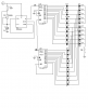
I'm currently working on a knight rider scanner. Got part of the scheme from internet (**broken link removed**) and extended it myself with another additional 4017 chip to use 8 LEDs in this "back and forth" configuration.

The problem is, I've got the timer to work, no problem there, can adjust the pulsing speed with a 500k potentiometer (just mounted a LED to pin 3 with a 680 ohm resistor), no problems there. But, when I connect pin 3 from the 555 timer to pin 14 from the 4017 chip (and of course the 0V, reset and enable pins to the 0V line), the output is kinda weird.

When I mount a LED to pin 3 (first output port of the 4017 chip), it should flash 1/10th of the time and be off 9/10th of the time. But, it flashes totally randomly and in variating brightness (also totally random). This stays the same when I mount more LEDs to the other ports, it's not how it's supposed to be. Does anyone know what I did wrong? Can't find any errors in my configuration. Btw, I'm using a 12 - 13,5v accumulator as a powersource.

Thanks =).
 
You do have a resistor in series with the LED? How much current are you trying to draw from the 4017 pin?
 
Post a schematic.
 
I think this is what you want?

pin 11 grounded = looked at several schematics but no ground on pin 11
might be problem??
 

Attachments

  • lights.PNG
    lights.PNG
    16 KB · Views: 3,847
The circuit will work alright if you cascade the counters. See ST (SGS/Thomsen) HCF4017 datasheet.
 

Attachments

  • Cascaded-counters.gif
    Cascaded-counters.gif
    17.8 KB · Views: 9,587
Last edited:
why the gates on the clk line??

first I have ever seen this done??
just curious.
 
first I have ever seen this done??
just curious.
Your circuit will not work.
The CD4017 datasheets from every American manufacturer shows how to cascade them with a gate. Bill Bowden shows how to cascade them with a Mickey Mouse gate made with diodes and a resistor.
 
pin 11 grounded = looked at several schematics but no ground on pin 11
might be problem??

Well I haven't ground pin 11 indeed. Should I do that?

Did you try to sequence two?

Yes that was my first attempt but it failed so hard I switched back to just one 4017 chip, but it still behaves very odd.

So well, the cascading comes for later. But now I'm not even getting one chip to work right.

I also found this tutorial:
**broken link removed**

Though they are using a different method to produce the pulses. But that shouldn't be an issue right?
 
Well I haven't ground pin 11 indeed. Should I do that?
Look at the datasheet. Pin 11 is an output on a CD4017. You never connect an output to ground.

Yes that was my first attempt but it failed so hard I switched back to just one 4017 chip, but it still behaves very odd.

So well, the cascading comes for later. But now I'm not even getting one chip to work right.
Post your schematic. I bet the CD4017 acts oddly because you forgot to use the supply bypass capacitors recommended on the datasheet of an LM555. The 555 draws up to 400mA from the supply each time its output switches that causes the supply to the CD4017 to drop so low that it malfunctions. A Cmos 555 does not have such a high current spike. A supply bypass capacitor (the LM555 datasheet recommends two capacitors) keeps the supply voltage from falling when the 555 output switches.
 
If your supply voltage is as high as 13V to 14V then you are probably smoking your CD4017 ICs since there is no current-limiting resistor for the LEDs.
The output current is probably 26mA then the output transistors in the IC have about 11V across them and dissipate a whopping (26mA x 11V=) 286mW.
 
Your CD4017 is not connected to 0V so it cannot do anything.
I don't see the important supply bypass capacitors.
 
Last edited:
Your CD4017 is not connected to 0V so it cannot do anything.
I don't see the important supply bypass capacitors.

Forgot to draw that in the circuit, on my circuit board I have the 0V pin grounded.
And what do you mean with the supply bypass capacitors?
Which capacitors should I use and where should I connect them to?
 
The datasheet for the LM555 says to use a 0.1uF ceramic capacitor plus at least a 1uf electrolytic capacitor as the supply bypass capacitors. If you don't then the circuit probably will not work properly.
 
I think you are talking about the 0,1uF capacitor which should be connected to pin 5 (control)?
According to the datasheets I followed it isn't nessecary to connect pin 5.
Plus, I don't see any problems with how my 555 chip functions, that one just works fine imo.
But if you're talking about another condensator connected to another input or something, could you please modify my circuit and post it? Else I still have no idea what to do :p
 
Hi,

that is what audioguru tried to make clear to you. The control pin has nothing to do with decoupling.

Attached is a proper decoupling circuitry for the NE555. If output current is close to maximum increase the value of C1 accordingly.

10µF is always a good value to work with.

Boncuk
 

Attachments

  • DECOUPLING.gif
    DECOUPLING.gif
    9.8 KB · Views: 506
The datasheet for the Cmos 555 Intersil's ICM7555 shows that an ordinary 555 causes a supply current spike of 400mA when its output switches.
The datasheet for National's ordinary 555 the LM555 shows that it needs two supply bypass capacitors to keep other ICs from crashing when the output switches.

Why don't people read the datasheets??
 
I did, but first off I'm not english / american and I didn't find anything about other IC's crashing because of a current spike.

But well, I'll get some new caps tomorrow and try it again ^^ Thanks in advance, I'll post it when I've got some results.
 
Status
Not open for further replies.

Latest threads

New Articles From Microcontroller Tips

Back
Top