Continue to Site

Welcome to our site!

Electro Tech is an online community (with over 170,000 members) who enjoy talking about and building electronic circuits, projects and gadgets. To participate you need to register. Registration is free. Click here to register now.

  • Welcome to our site! Electro Tech is an online community (with over 170,000 members) who enjoy talking about and building electronic circuits, projects and gadgets. To participate you need to register. Registration is free. Click here to register now.

Weird 4017 behaviour

Status
Not open for further replies.
I did, but first off I'm not english / american and I didn't find anything about other IC's crashing because of a current spike.
I am also not English/American, I am a Canadian.
Some English/American people have such a strong accent that I don't know what they are saying.
Maybe you should translate the datasheet into your language or find a datasheet that is written in your language.

The datasheet for National Semi's LM555 clearly says:
"Adequate power supply bypassing is necessary to protect
associated circuitry. Minimum recommended is 0.1μF in parallel with 1μF electrolytic."​
 
I posted a link on the 555

In this link it specifically talks about decoupling caps. Even mentions for the 7555.
I guess we not gots good english for Smonjirez.
He not realize that what Audioguru posts is pretty much from the bible of electronics.
I am amazed at his knowledge of electronics.
Still wonder about which resistor is supposed to be higher in value
pin 8 to 7 or pin 7 to 6.
have tried several combos, trying to obtain as close to 50% duty.
then inserting the diodes across resistors??
still learning on this end.
 
Night Rider

Dude worry no more this is the real Knight Rider Schematic and it works.
In this unit 2 LED's side by side move back and forth making a more visible scanner. Excuse my rough drawing it was fast and furious
 
Night Rider

"Woops second post forgot the attachment"

Dude worry no more this is the real Knight Rider Schematic and it works.
In this unit 2 LED's side by side move back and forth making a more visible scanner. Excuse my rough drawing it was fast and furious
 

Attachments

  • Night rider.pdf
    156.7 KB · Views: 337
He not realize that what Audioguru posts is pretty much from the bible of electronics.
I am amazed at his knowledge of electronics.
Thanks.
I am a geek. Electronics was my career. Now I am a retired bum.

Still wonder about which resistor is supposed to be higher in value
pin 8 to 7 or pin 7 to 6.
have tried several combos, trying to obtain as close to 50% duty.
You had the resistors backwards sometimes. On the simulator you had them correct and got a pretty good square-wave.

You must understand how the 555 oscillator works:
1) The timing capacitor charges through both resistors in series.
2) The timing capacitor discharges through the resistor from pin 7 (the discharge transistor) to the capacitor.
3) So if the resistor from pin 7 to pin 8 is small and the resistor from pin 7 to the capacitor is large then the charge time and discharge time are almost the same.
4) Don't make the resistor from pin 7 to pin 8 too small or the discharge transistor will have a current that is too high.

then inserting the diodes across resistors??
Diodes are used for Pulse-Width-Modulation or if you want the duty-cycle to be exactly 50:50. You had the capacitor charging through 310k and discharging through 300k which is a pretty good square-wave.
 
"Woops second post forgot the attachment"

Dude worry no more this is the real Knight Rider Schematic and it works.
In this unit 2 LED's side by side move back and forth making a more visible scanner. Excuse my rough drawing it was fast and furious
The old Knight Rider had a light display that went back and forth.
Your LEDs are just a Chaser that goes around and around and not back and forth.
 
thats called a DAY RIDER

back n forth = knight rider
chasing leds (one direction) GAY DAY RIDER -- lol
no reference intended
 
Knight Rider revised

Hello fellow Nuts, i must be excused from making mistakes it was late and in my hast forgot to look at changing the output configuration so you could get your delusional brains around the principle.

I will explain:
The 4017 can not by it self go back and forwards as it is a simple dive by 10 counter it is in fact an illusion its all in the way the LED's are connected- it just appears that the LED's are scanning left to right and right to left.
What i have done is actually count from 0 to 4 with the LED's arranged in a left to right pattern and then count from 5 to 9 with the LED's arranged in a a right to left pattern. Presto- the LED's operate one way then in a reverse direction!

If you now look at the outputs of the 4017 you will see them shown wired from top to bottom of the drive transistors from 0-9 i have arranged the sequence as 0, 9,1, 8,2,7,3,6,4 and 5. So the LED's are scanned from left to right for 0-5 counts and from right to left for 5-9 counts.

The connection of the LED's is also unusual when the 0 output is high LED 1 and LED 3 light up and there is a separation of LED 2 between them. When the 1 output goes high LED 2 lights as well as LED 4 and so on.

Have fun.
 

Attachments

  • Night rider.pdf
    219.5 KB · Views: 262
The old Knight Rider had a light display that went back and forth.
Your LEDs are just a Chaser that goes around and around and not back and forth.
Yes it was late and i did not show the correct output configuration. I am like most Guilty of to many hours on the NET.
I have uploaded a new drawing and explanation to show how a 4017 can work in this fashion.
 
different take on knight rider circuit

add the Vcc, grd, 55 timing components and you then have a back n forth flasher without all the confabulated diode arrangements.
instead of knight rider call it a tribute to the TTL Gods
Ol Forrest Mims circuit
 

Attachments

  • knight rider.PNG
    knight rider.PNG
    29.8 KB · Views: 303
Hi Greggles,
You have some capacitors with the tiny value of 100pF. They should be 100uF?
 
Really

The original circuit had the correct values. this post was to correct the outputs of the 4017, really! have you nothing better to contribute other than debate the clock. the 4017 was the subject.

If you need help with something i will show you how, but not if your going to be a serial pain in the ass.
The 4017 probably will not work properly with the wrong value for the clock timing capacitor and the wrong value for the supply bypass capacitors.

Nobody has to help you correct your mistakes. There are probably many other people who are thankful for my corrections.
 
Just for Audioguru

:mad: Again! I reiterate the original drawing had the correct values for the clock and the decoupling. The second post was to correct the 4017 outputs.

As Mr AudioGuru is so pedantic and cannot read and needs to feel he has to correct me, i have for his benefit filled in the gaps.

Yours Sincerely
Greg Brechelt MSc, BEng MB NZEI
 

Attachments

  • Night rider.pdf
    224.7 KB · Views: 221
Do you know what back and forth means?

looking at your output LEDs, you have 10 pairs of LEDs (a pair is 2)
no back and forth motion that I can see. Just each time an output goes high tow LEDs (1 pair) lights up.
back and forth is the LEDs light up in sequence (one comes on while the previous one goes out) in a "to the right" sequence then reverse by sequencing from left to right.
all I see are a bunch of LEDs comming on in pairs.
If you post a schematic at least try and get the components in the right order and take suggestions by not critizing a knowledgeable person like Audioguru.
and what is with MSc, BEng MB NZEI
looks like a text message of some kind?
"message being ?? ??"
 
Seems everyones an expert:

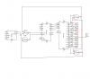
The 4017 can not by it self go back and forwards as it is a simple divide by 10 counter it is in fact an illusion its all in the way the LED's are connected- it just appears that the LED's are scanning left to right and right to left.
What i have done is actually count from 0 to 4 with the LED's arranged in a left to right pattern and then count from 5 to 9 with the LED's arranged in a a right to left pattern. Presto- the LED's operate one way then in a reverse direction!

If you now look at the outputs of the 4017 you will see them shown wired from top to bottom of the drive transistors from 0-9 i have arranged the sequence as 0, 9,1, 8,2,7,3,6,4 and 5. So the LED's are scanned from left to right for 0-5 counts and from right to left for 5-9 counts.

The connection of the LED's is also unusual when the 0 output is high LED 1 and LED 3 light up and there is a separation of LED 2 between them. When the 1 output goes high LED 2 lights as well as LED 4 and so on.

print the attached PDF and build it. if im wrong ill suck it in and resign.
and as for my credentials you would do well to not scoff at someone who has an education in this field. my retoric to Mr Audioguru was for the replies on the clock and the fact that the debate is for the correctness of the 4017 as a scanner and not just a continuous loop counter.
Now get bread boarding or use what i give my students to sim on the computer by downloading yenka at Yenka.com select home user under registration and you can use it for free. I do not have a go at Mr Audioguru's helpful hints as i have read many of his responses and find him well schooled, but when the original schem had the correct values and was advised of same do you think it apporpriate to correct me on such trivia? Oh and yes we do get things wrong in this line of work thats why we have debuggers the last circuit had a design fault one output was incorrect, this attached schem has the fix. So who are you?
 
Hi Eric

yes it works, although some what old technology now, a nice little pic would do just as well and give a few more patterns for some better effects.
Nothing worse than a little bit of knowledge, I would rather creative banter, I will stick around on this site for a while and maybe MrDeb and Mr AudioGuru can become my friends and respect who I am and who knows what we may achieve.
Life should be a sharing learning process.
 
Diodes are usually used to make a CD4017 light the same LEDs back and forth.
you used some outputs to drive LEDs forward and used other outputs to drive different LEDs backwards. It is your positions of the extra LEDs that make the appearance of back and forth.
 
Status
Not open for further replies.

Latest threads

Back
Top