Continue to Site

Welcome to our site!

Electro Tech is an online community (with over 170,000 members) who enjoy talking about and building electronic circuits, projects and gadgets. To participate you need to register. Registration is free. Click here to register now.

  • Welcome to our site! Electro Tech is an online community (with over 170,000 members) who enjoy talking about and building electronic circuits, projects and gadgets. To participate you need to register. Registration is free. Click here to register now.

Document this 555 / 4017 on/off circuit

Status
Not open for further replies.

ThomsCircuit

Well-Known Member
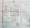
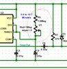
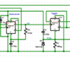
The author of this circuit has what appears to be a great solution I and others are trying to do with a 555. That is to trigger and reset the ic with the same momentary button.
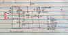
His documentation is a bit difficult to read and leaves out some explanation. On off 555 & 4017
From what I can tell the touch plate sends a pulse to pin 2 of the 555 thus starting the process and energizes the coil of the relay. What I do not understand is how does the 2nd press of the plate reset the 555 via low to (pin4)? And if left alone will the 555 time out and reset on its own after the calculation of R3 & C2 = delay is met.
Thank you in advance for the assistance.
 

Attachments

  • Single-Touch-on-off-switch-circuit.jpg
    Single-Touch-on-off-switch-circuit.jpg
    202.3 KB · Views: 415
Last edited by a moderator:
The 555 timer is set up to make a single shot pulse each time the touch pad is touched. It then goes back to ready state.

the cd4017 is a decade counter. Each pulse into pin 14 from the 555 advances the output. When turned on, output #0is high (pin 3). When the touch plate is touched, the 555 pulses one time and the cd4017 advances to output #1 (pin #2). Note Pin#2 is connected to the relay pass transistor which energizes the relay coil.

on the next touch of the pad, the cd4017 BRIEFLY advances to output #2 (pin#4). But pin 4 is connected to cd4017 reset so cd4017 immediately turns on output 0 (pin 3) again - back to beginning. Relay is off.
The 555 acts like a "switch denounce circuit" to make sure one press = one pulse.
The cd4017 is common so most people have one sitting around but in 5is case, it is acting more like a flip-flip than a counter. I would design around a flip flop instead of a 4017.
 
Oh this is great! What if the plate is touched turning on the coil then left alone. Would the 555 automatically reset, turning off the relay after the cap/resistor delay expired?
 
Oh this is great! What if the plate is touched turning on the coil then left alone. Would the 555 automatically reset, turning off the relay after the cap/resistor delay expired?

no, the 555 tuns off about 1.1 seconds after you touch the plate and the cd4017 "remembers" the current state forever (until the touch plate is touched again to trigger the 555 one more time). Then the 4017 remembers that new state forever.

did you need another design? Other options are possible (two 555 timers in series to toggle the light for a specific time - then a 4017 is not needed).
 
Bummer and yes I do.
I had my suspicion that the 555 was not being used the way I needed it to.
I do have a setup that works but I need to wait for some parts to arrive, test it, then post any issues i run into. I'll show it to you but it's not tested. The only part i have a doubts about is energizeing pin4 before pin2 is triggered.

So this first slide is a touch pad (tcp442) that runs on 5.5v. It latches at 4.5 to the dual color led and the 4093 and a peizo buzzer.

Pressing the touch changes the led from red to blue and sounds the buzzer for .750ms.

Pressing it again the touch goes low changing the led to red and another .750ms buzz.

I need to turn a 5v relay on and off with each press. I also want the relay to turn off on it's own after a delay has expired so I implimented a 555. That is the second slide.

To start the 555 I send the .750ms pulse to the 555 from the output of the 4093. At the same time pin 4 of the 555 is held high from the 4.5v at the touch pad.

The possible issue is that pin2 going low before pin4 going high. But I have not tested it. It may work fine. So I'm wondering if and then how can I add a fraction of a second delay to the triggering of pin2. So pin4 makes its connection to the 555 first and then pin2 is pulsed.

I placed 2 red "x" where the first slide would connect to the second slide. Again, thank you for your time.
 

Attachments

  • 20200417_154349.jpg
    20200417_154349.jpg
    1.6 MB · Views: 205
  • 20200424_144944.jpg
    20200424_144944.jpg
    1.2 MB · Views: 201
Last edited:
did you need another design? Other options are possible (two 555 timers in series to toggle the light for a specific time - then a 4017 is not needed).
[/QUOTE]
Can you give your opinion?
 
did you need another design? Other options are possible (two 555 timers in series to toggle the light for a specific time - then a 4017 is not needed).
Can you give your opinion?
[/QUOTE]
This is way to complicated for paragraph explanation.can you make a block diagram of what needs to be accomplished and when (just the lights, buzzers and relays). Once those timings and functions are assigned, we can figure out some logic options to make it happen.
 
Can you give your opinion?

Hi

Here is my suggestion on a design.
See circuit below for the following description.

I've used a TLC555 CMOS Timer, a CD4013B D-Flip Flop and three 2n7000 mosfets.
I've shown a pushbutton to activate the circuit but a touch switch like yours can be easily substituted as shown by dashed lines.

When the switch is pressed, the switch is de-bounced by U1A which then produces an output pulse. The pulse causes two things to happen:
1) U1A pulses its Q output and toggles U1B which activates the relay, lights the GRN led, and triggers a RC pulse that sounds the Buzzer for approx. 700ms.
2) U1A also pulses its Qbar output and triggers the 555 timer. The timer begins running.

If the switch IS NOT pressed again before the timer expires, a pulse is produced by the timer output circuit that then resets U1B. This deenergizes the relay, lights the RED led, and holds the timer in "reset".

If the switch IS pressed again before the timer expires, a pulse is produced by U1A. The pulse causes two things to happen:
1) U1A pulses its Q output and toggles U1B which de-activates the relay and GRN led. It also places the 555 timer in "reset mode".
2) U1A also pulses its Qbar output and trys to triggers the 555 timer. But the timer is in "reset mode", so the trigger pulse has no effect.

The circuit is now ready for the next cycle.

I've shown a mosfet driver for the buzzer because it isn't clear how much driver current it requires.
The LEDs are driven direct from the DFF outputs, so they will have to be of low current type (each less than 5ma). If they require more current then a driver circuit will need to be incorporated.

The timer is adjustable between approx 10-15 minutes but I hope you don't need accuracy. This type of timer is not for precision applications.
The circuit should operate with a supply between 3-15v.

eT

Below shown after timeout.

1587858259931.png


Below shown with button pressed before timeout

1587858415982.png
 
This looks wonderful. I saw you posted it to the other forum as well. Super. I've gone through and made sure I had all the necessary ic's, caps, and resistors.

The touch pad I use works on 5.5v and outputs a 4.5v positive latch.

The relay is 5v and requires 70ma to engage the coil

The speaker is 5v. I also have 3v speakers

I have a question about these 2 resistors. The 1M wiper and the 1.6M resistor. Do I need both? I've not seen any samples with two resistors in line to control the delay off.

I will be ordering
2N7000 mosfets
1M ohm ½ watt resisters
1.5M ohm ½ watt resistors (can't locate 1.6M)
CD4013BE flip flop
0.01uF & 0.22uF caps

Everything else I have
 

Attachments

  • 20200425_204218.jpg
    20200425_204218.jpg
    340.1 KB · Views: 201
Last edited:
This looks wonderful. I saw you posted it to the other forum as well. Super. I've gone through and made sure I had all the necessary ic's, caps, and resistors.

The touch pad I use works on 5.5v and outputs a 4.5v positive latch.

Does that mean the output remains on as long as it is touched? If so, that's ok.

The relay is 5v and requires 70ma to engage the coil

Perfect

The speaker is 5v. I also have 3v speakers

perfect

I have a question about these 2 resistors. The 1M wiper and the 1.6M resistor. Do I need both? I've not seen any samples with two resistors in line to control the delay off.

Yes. You need both. The 1M linear potentiometer adjusts the resistance to set the time delay. The 1.6M is a limiter. Without the limiter the potentiometer could short the to cap.

I will be ordering
2N7000 mosfets
1M ohm ½ watt resisters
1.5M ohm ½ watt resistors (can't locate 1.6M)
CD4013BE flip flop
0.01uF & 0.22uF caps
Everything else I have

Do you have the CMOS version of the 555? That would be part number TLC555 or LMC555 or TS555.
The NE555 would not be the correct one.

The 2n7000 should be the TO-92 version (looks like a BJT transistor)

Questions:
1. Please note, I haven't tested this on a breadboard and it should be.
Are you able to do this?
2. How will you make the final version? Will it be A PCB?
3. What will you use for a power supply?

eT
 
Questions:
1. Please note, I haven't tested this on a breadboard and it should be.
Are you able to do this?
2. How will you make the final version? Will it be A PCB?
3. What will you use for a power supply?

Yes I will test it on a BB
yes the final will be on a PCB board
I have a 12v 10amp power suppy. I'm stepping a leg of it down for this circuit to 5.0 volts.
I'll order the correct 555 chip and I'll make sure the mosfet is T0-92

I just printed it out so I can see it better. Let me know if I can eliminate the mosfet for the speaker (and how)
 
I have a 12v 10amp power suppy. I'm stepping a leg of it down for this circuit to 5.0 volts.

everything can handle 12V, except your buzzer. Just put a resistor in-line with your buzzer.
 
I've shown a mosfet driver for the buzzer because it isn't clear how much driver current it requires.
The 5v buzzer is 30ma
This is what mine looks like but 5v
 

Attachments

  • Screenshot_20200425-234230_Drive.jpg
    Screenshot_20200425-234230_Drive.jpg
    474.2 KB · Views: 184
I've used a TLC555 CMOS Timer, a CD4013B D-Flip Flop and three 2n7000 mosfets.
Regarding the flip flop. I've identified all the pin outs on your diagram except for the ones I've marked in this image.
 

Attachments

  • 20200426_001636.png
    20200426_001636.png
    30 KB · Views: 190
Hello

I thought about this design a little more and believe this a better way to go.
This design works the same as before except I replaced all the mosfets with a single TBD62003A "MOSFET Array" chip.
Though it adds a chip, the benefit is that the drive current for each device (Relay, LEDs, Buzzer) can now be up to 200mA per device.
So if you need brighter LED's, or more power for the relay or buzzer, you have plenty capacity.
I've also incorporated your requirement for the buzzer to sound both when the relay energizes or deenergizes.

BTW- I also enlarged the 4013B graphic so the pin numbers are easier to read.

See Below.

1587925005434.png


The following shows a button press every 25 seconds.
1587925086433.png


The following shows a single button press.
1587925225761.png
 
So if the switch is held high instead of a pulse the circuit will still function? This would let me adapt this to other switches in the room.

The current design produces a single pulse if the button is held down. If your touch switch produces a pulse, the pulse would need to be longer than the pulse incorporated in the design. Can you confirm how your touch plate output works in both latch and pulse modes?

eT
 
Status
Not open for further replies.

Latest threads

New Articles From Microcontroller Tips

Back
Top