Continue to Site

Welcome to our site!

Electro Tech is an online community (with over 170,000 members) who enjoy talking about and building electronic circuits, projects and gadgets. To participate you need to register. Registration is free. Click here to register now.

  • Welcome to our site! Electro Tech is an online community (with over 170,000 members) who enjoy talking about and building electronic circuits, projects and gadgets. To participate you need to register. Registration is free. Click here to register now.

waterfall printer

Status
Not open for further replies.
sorry for blurry shematics how can i put a better image. i just print screened the schematic put on paint.

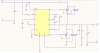
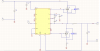
one of my images is named 33v.jpg it is the schematic for my 3.3v power supply.


i've included images again i dont know if its better
 

Attachments

  • 3_3v.png
    3_3v.png
    42.2 KB · Views: 336
  • 5v.png
    5v.png
    40.7 KB · Views: 313
  • solenoid power supply.png
    solenoid power supply.png
    98.7 KB · Views: 392
Last edited:
sorry didnt have the parts listed these are the parts to use attached
 

Attachments

  • solenoid circuit.txt
    52 bytes · Views: 264
  • 3_3.txt
    242 bytes · Views: 248
  • 5volt.txt
    241 bytes · Views: 232
A variation on the suggestion in post #52 :-
If there are only a few fixed images to print then you could represent the data as drilled/punched holes in a metal/plastic sheet, like the old Pianola music rolls for player-pianos. Run the sheet at a steady rate past a row of pressurised nozzles. No need for any electro-valves.
 
That's actually a really good idea alec, I think I like it better than the solenoid version.
 
As i had surgested back in post #52 it would have to be the simplest method, although limited to design artwork.

The biggest problem i see is leakage around the edges of the sheet, but maybe some rubber wheels out at the edge might solve the problem.

I do intend on trying a small template sheet to see what the results are.
Most likely i will just use a cut away section of a PVC pipe and tape the template to it for a test.
It will be a bit of a trial and error with hole size and rpm of rotation, if all works by hand rotation than a small stepper motor would do the rotarion nicely.

Pete.
 
Attached is VB6 source code alongwith Arduino sketch

Hi,
I am attaching the VB6 source code and Arduino sketch for all who want to improve this program . I will request maintain my name in the 'About Box' and wherever you share keep following information in it.

Khalid Farooq Khattak
engr.khalid.khattak@gmail.com
Pakistan"

I will also request you as i have no time to work on this project and the code is not maintained in well formatted, so forgive me for this.
You can open the project in Visual Basic 6. Keep improving the program and keep posting the updates.
Regards
 

Attachments

  • VB6 Graphical Water Fountain source code.zip
    17.8 KB · Views: 335
So far no bugs found..but i have abandoned this project..any newbie in visualbasic can make it more better. Thanks for thanking me:)
 
Is their any DIY version of solenoid valves?
Not realy. There have been some ideas, but nothing fast enough. You need high speed valves and constant pressher to get this to work. The rest easy.
Andy
 
Having designed machines which fill bottles, looking at the videos I'd say your outlet tubes from the solenoids are way too long.

You won't get a sharp on/off flow - there will be fluid left in the outlet tubes which you have very little control over - some may stay in with its own surface tension, some will drain gradually as air enters the tube.

I've had great fun in the past trying to do a similar thing but for a totally different application (medical filling applications).

I've not read the whole thread but .......

Some solenoid valves require a slight back pressure to open quickly and effectively
The more pipe after the valve, the less the accuracy of the fluid dispensing. A short burst into an empty tube will result in an empty tube as the fluid will dribble down the side of the tube, a long burst may result in a full tube with all air expelled but the surface tension / vacum may hold fluid in the tube
If the liquid is pressurised, consider one way valves in the outlet tubes. Pressurising wouldn't work very well though as you ideally want the fluid to drop out under gravity.

If you took the pipes off the bottom of the solenoids and lined them all up next to each other (at the expense of resolution), this would take away a lot of the variables associated with the pipe issues when testing.

I've worked on pumped systems, pressurised systems, gravity fed systems, piston systems, peristaltic systems, vacuum mixing systems and weight based systems and had to meter fluids down to a millileter and fluid is not the easiest of materials to work with :p (add in varying viscosities which themselves vary based on the temperature of the workplace and you end up pulling your hair out)
 
Oh and to add to the above, try to use a trough header tank with a ball valve (or electronically / electrically) filling system to keep a minimum of around 1 -2 feet of head in the tank. This will ensure a constant pressure to the valves. If the fluid level in the tank varies, so will your accuracy. One of the filling machines we have with the greatest accuracy uses this arrangement - constant head and simple pneumatic operated outlet valves.
 
Please post your ideas. I am stuck in finding good solenoid valves. and i am rather poor to purchase costly one... Is their any DIY version of solenoid valves?
Regards

I have mentioned this idea in the past but it has not gotten any traction.

Use the header tank as mentioned below but do not put solenoid valves on the outlets. Instead have the outlets running all the time. Use something like a mechanical solenoid or a stepper to rotate each outlet so it points down or rotate a bit to make the water hit a catch return basin.

This eliminates the on/off problem with solenoid valves. But you have to deal with rotating the outlets and it may have its own set of problems.
 
So this is my idea for a DIY solenoid/valve. I'll use the polarity to slide a metal bar back and forth. I'd drill a hole in the slide to make an opening when given a polarity, and a closed valve with the opposite polarity. I believe this can be done with an arduino. My first tests will begin Monday.
 
Status
Not open for further replies.

Latest threads

New Articles From Microcontroller Tips

Back
Top