hello my name is Kudzi I'm a young vibrant african student studying film n
photography in Botswana., recently was given the task to shoot a moving time-lapse sequence,
Time-lapse photography is a technique whereby the frequency at which film frames are captured (the frame rate) is much lower than that used to view the sequence. When played at normal speed, time appears to be moving faster and thus lapsing.
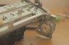
I then tried to do this with a small table top dolly like the 1 below

Here is where the problem comes
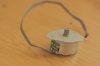
manually moving the camera & taking the photos is kind of tedious & my increments as regards to moving the dolly are not consistent., i'v read & even seen videos of motorized dollies made from stepper motors salvaged from old printers & scanners, so i decided to try it out too, Problem is i Have no idea how stepper motors are controlled by the controller boards
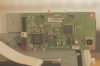
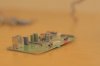
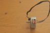
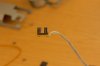
However i managed to get an old Usb Epson Stylus C42UX inkjet printer & got some really nice motors as-well as a main board, what i would like to do is to get the motors running from a smaller power supply like say maybe 2 Cellphone batteries & be able to drive the table top dolly in lateral motion
in conclusion
i just want to be able to run the motors without using the mains power i have 3 pdf with the schematic of the board. pliz assist me on how i can achieve this with the materials i have thanx
photography in Botswana., recently was given the task to shoot a moving time-lapse sequence,
Time-lapse photography is a technique whereby the frequency at which film frames are captured (the frame rate) is much lower than that used to view the sequence. When played at normal speed, time appears to be moving faster and thus lapsing.
I then tried to do this with a small table top dolly like the 1 below
Here is where the problem comes
manually moving the camera & taking the photos is kind of tedious & my increments as regards to moving the dolly are not consistent., i'v read & even seen videos of motorized dollies made from stepper motors salvaged from old printers & scanners, so i decided to try it out too, Problem is i Have no idea how stepper motors are controlled by the controller boards
However i managed to get an old Usb Epson Stylus C42UX inkjet printer & got some really nice motors as-well as a main board, what i would like to do is to get the motors running from a smaller power supply like say maybe 2 Cellphone batteries & be able to drive the table top dolly in lateral motion
in conclusion
i just want to be able to run the motors without using the mains power i have 3 pdf with the schematic of the board. pliz assist me on how i can achieve this with the materials i have thanx