Continue to Site

Welcome to our site!

Electro Tech is an online community (with over 170,000 members) who enjoy talking about and building electronic circuits, projects and gadgets. To participate you need to register. Registration is free. Click here to register now.

  • Welcome to our site! Electro Tech is an online community (with over 170,000 members) who enjoy talking about and building electronic circuits, projects and gadgets. To participate you need to register. Registration is free. Click here to register now.

Regarding Stepper Motors and Printer PCB

Status
Not open for further replies.

Menticol

Active Member
Hello guys!

I'm building a small CN laser engraver, based solely on old printer scraps. So far is looking like this, but i'm stuck on a point and I wonder if you could give a hand.

IMG_1458.JPG

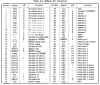
My goal is driving the stepper motors using some components of an old EPSON printer PCB. Unfortunately I couldn't find the datasheet of the motors controller, SMA7023M.

IMG_1583.JPG

This is the controller, each branch of 6 wires go to its respective stepper motor.

IMG_1584.JPG

The only similar datasheet that I could found was for the SMA7022MU but i'm not sure if it would work.

The markings on the stepper motors are equally obscure.
IMG_1581.JPG

Another question is, would be possible to simply power the board up and simply injecting external pulses on the adequate microcontroller outputs, faking the microcontroller orders and make stepper motors turn? I like the idea because the board is well built, and already has all the neat molex connectors, protection circuitry etc.

Any advice would be extremely appeciated
 
Thank you by your input KISS.

The thing is getting hairy, I never worked with double sided PCB's before. Some of the motor leads go to the 7023 coupled by 6 ceramic capacitors and 2 diodes. The other leads go to a network of transistors, I don't understand their function (I supposed that the 7023 would do all the driving).

IMG_1588.JPG


The six remaining legs from the 7023 get lost into an network of resistors that also are connected to the transistors mentioned before. Then they seem to go to an elongated component, and finally the microcontroller. I don't know what is that elongated component, there are two of them labelled as RM1 and RM2, each one reference L307 9252. What is that component?

IMG_1590.JPG
 
Last edited:
If anyone needs it, I've found the beautiful service manual fot this printer. It also includes the datasheet for every chip.

Unfortunately my PCB suddenly stopped working, I suspect it was ESD damaged. I'll check if the motor driving stage still works
 

Attachments

  • Epson LX-810 LX-850 Service Manual.pdf
    4.1 MB · Views: 1,107
  • pinout.png
    pinout.png
    121.7 KB · Views: 548
Last edited:
The 7022 has a larger package and is meant for heatsink mounting etc.

Looking at your PCB it seesm the 7023 is just used as a sequencer, with external transistors as the unipolar drivers. That's an ancient setup, and probably means the printer was halfstep drive which is really noisy with badly vibrating movement compared to the modern standard of microstepping.

Seriously, I would junk the PCB and build/buy some microstepping drivers. :)
 
RM may stand for Resistor Module or more typically in the US RN for resistor network. See: **broken link removed**

You will LIKLEY find a resistor connected to the band side.

9252 is likely a date code. Year 1992, week 52.

Almost any configuration can be placed there. A good use for one is to provide pull up resistors. In TTL, you can use a pull-up and pull down.

Epson's manuals are nice, but they are not entirely complete (250 pgs+). I just printed one in color. Gonna try my hand at fixing my printer for fun: ADF gearing broken (Epson design issue), CIS (sensor), I hope that's the problem, Waste Ink tank (probably will replace)

Epson redesigned the gears. MY feeling is they should have recalled it. ADF broken.
CIS sensor. About a cm vertical black line down the page using table. Prints fine.
End of life on waste ink - was successfully reset.

Not much info on troubleshooting/replacing the CIS sensor, though.

And you need the Epson adjust Program. That's a tougher problem.

What I HATE is things like, once the ink pads are at end of life, you can't do anything. If a color cartridge is missing, you cant print in B&W.

Support isn't too good either.

The manual goes into excruciating detail about how to take it apart and replace parts to the point the pics are in color. The specifications are detailed as well. No component level servicing, no parts list, no exploded view. I got the view elsewhere.

The software could be modified so easily so that two sided copying can be handled from from the single sided ADF. All they need to do is to allow a suffix: e.g. FilenamePPPS.pdf where PPP is page and S is suffix. S could be A or B for Odd or even pages. Then they need to allow increment by 2.
page001a, page003a,page005a for the ADF odd pages
and
page002b, page005b, page007b

And it would be SO much easier to get a double sided PDF. It is possible with contortions using RenameMaster. Then starting from page001, page002, page003 and running a program to add an "a". Then scan into another directory side B as page001, page002, page003 and then add a "b" to every file.
Then combine into a singe directory page001a, page001b, page002a, page002b
and combine via Acrobat.

==

Look at the connectors only. Find the two wires that should go to power on the motor.. That's your start.
You also should be able to measure resistances back to the chip or driver transformer with the motor connector pulled.
 
I have done that a couple times. Cut the traces on the MOSFET gates and LPT data bits. If there are pull down resistors on the MOSFET gates, use them. Run jumper wires from the MOSFET gates to the LPT data bits. Then you can send quadrature patterns on the data byte to drive the motors. You will probably want INPOUT32.DLL for easy access to LPT1. You can use control bits to fire the laser.
 
This is the motor control part of a C++ program that scanned a black and white bitmap picture and fired a relay / solenoid to engrave a picture on aluminum. You could use that part to control the laser. At the end is a GW Basic program to test stepper motors.
This was from long ago. I didn't remove my notes.
 

Attachments

  • PIO.txt
    14.7 KB · Views: 244
Hola Menticol

I replaced the original micro and the logic IC used in an Epson LX850. After programming my 18F452 it worked OK.

Found very convenient to see "how it works" with all the electronics and motors out of the plastic frame and covers.

THen I made it to carry out the built in test. (It is amazing how fast the whole thing moves).

In my case I found a must to keep all limit sensors connected to avoid running past the mechanical end with the stepper steaming full ahead.

THe schematic I found in the web was a miserable scan so I had to do reverse engineering and create my own one.

Desoldering and soldering the new micro was basically all what I did. The rest was pure programming.
 
Hello guys! Sorry by taking so long, I tried to make a decent amount of progress before showing my face here again.

At first I thought that all I would have to do is sending X number of pulses, and the driver PCB would translate them into X number of steps. But well, I was very wrong. All the stepping was made inside the microcontroller, so having or not having the board made no difference.

IMG_1596.JPG

I tried ClydeCrashKop advice, just the existing transistors instead of the whole board. Unfortunately during this step I short circuited the PSU and the board got wrecked, my bad. Thank you by your code, I'll try it when the hardware is finished.

Following KISS advice I've identified the corresponding motor pins to make my own driver, based on a ULN2803 and a parallel port.

IMG_1625.JPG

IMG_1626.JPG

They work, now I'm adapting them to the existing printer belts and structure holes. Trying to remove the gears destroyed the previous stepper motors, so I opted by the horrendous solution you are about to see.

IMG_1639.JPG

A problem I'm facing now is that the motors don't have any decent torque. At this moment I'm only turning on only one coil at a time. I guess this method is very crude. If you can recommend me a better method or some decent reading about the topic I would appreciate it a lot.

By the way I checked Mr RB driving boards and they look damn good (I don't want to be a sycophant, I just checked the finished CNC's using them). Unfortunately they are beyond my budget.

Atferrari made me think about a fact I didn't contemplated: How precise the stepper motors tend to be? can I expect that the stepping amount to be uniform, or a feedback sensing system would be required?


Thank you by all your inputs guys
 
Last edited:
...
A problem I'm facing now is that the motors don't have any decent torque. At this moment I'm only turning on only one coil at a time. I guess this method is very crude. If you can recommend me a better method or some decent reading about the topic I would appreciate it a lot.
...

If you are happy with full-step drive, you should drive TWO coils on at all times, not one.

This is a "full-step" drive sequence using one coil;
1000
0100
0010
0001

This is also "full-step" but has a LOT more torque;
1100
0110
0011
1001

...
By the way I checked Mr RB driving boards and they look damn good (I don't want to be a sycophant, I just checked the finished CNC's using them). Unfortunately they are beyond my budget.
...

Thanks for the nice words. :) Now I understand better that you are in Colombia and on a tight budget it makes more sense why you are doing it this way instead of just buying some motors and drivers from ebay.

...
... How precise the stepper motors tend to be? can I expect that the stepping amount to be uniform, or a feedback sensing system would be required?
...

Your little motors will have 24 or 48 full steps per rotation. You can check that out by powering one coil with DC, and seeing how many "detents" the shaft makes when you turn it by hand. 12 detents/rev will mean there are 48 steps/rev, as there are 4 full steps to each magnetic phase "detent".

They will position "accurately" to a bit better than one full step. If you know how many full steps per rev you have, you adjust by calcuating linear machine movement in mm per rev.
 
Status
Not open for further replies.

Latest threads

New Articles From Microcontroller Tips

Back
Top