Continue to Site

Welcome to our site!

Electro Tech is an online community (with over 170,000 members) who enjoy talking about and building electronic circuits, projects and gadgets. To participate you need to register. Registration is free. Click here to register now.

  • Welcome to our site! Electro Tech is an online community (with over 170,000 members) who enjoy talking about and building electronic circuits, projects and gadgets. To participate you need to register. Registration is free. Click here to register now.

Voltage Multiplier Circuit Design

Status
Not open for further replies.

ayaz15m

New Member
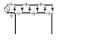
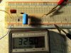
I have made a 3 stage voltage multiplier. My input is from the outlet so 120 V ac. I measure my output from the first and last capacitors of the bottom row as shown in the image. The output I am getting is 120 V dc. From the equation Vout(dc) = Vin(ac)*sqrt(2)*number of stages. With this equation I should be getting around 500 V dc theoretically. I am not sure what is going on, anybody have any insight. Thank in advance.
 

Attachments

  • Circuit.png
    Circuit.png
    16 KB · Views: 446
First, using mains voltage is dangerous! You should at least be using an isolation transformer.
With that said you will need some sort of a load on the multiplier circuit to get the wright output voltage.
You are reading an open circuit voltage.
 
Your Circuit is Not Correct.
A Load Resistor is Not Needed, the Meter is a Load.

Build This One, it will work:
 

Attachments

  • Multiplier.png
    Multiplier.png
    669 bytes · Views: 595
A Load Resistor is Not Needed, the Meter is a Load.
The meter may not be enough of a load to fully charge the caps there for you will not get a true reading.
Meters have a very high resistance.

You may need a load.
 
No it wont.
With Only the Meter as a High Resistance Load, the Ouput will charge up to the value shown.

With a Lower Resistance Load, the Output Voltage Will be somewhat Lower, Depending on the Capacitor Values.
( As a Result of Capacitive Reactance Verses the 50 or 60 Hz input Frequency)
 
I was wanting to test the multiplier out to see if I was getting the correct output. Is my output not being multiplied because it is directly from the wall and I am not using a transformer? My actual goal is to take a neon sign transformer which gives me 9500 V and put it through my multiplier to get close to 40,000 V dc. I am using high voltage capacitors and diodes both are rated 20kV.

chemelec:
What kind of circuit is that, how much will my input be multiplied by? Because I have not seen that circuit design, all the research I have done on voltage multipliers circuits show circuits like the one I posted above.
 
The Circuit I Posted is a Typical, Quadrupler Multiplier Circuit.
The Output will be 5.6 Times the RMS Input.

Your Circuit is Definately NOT correct.

Build it and it will work.

The Diodes should be rated at 200 Volts MINIMUM.
The Caps should be "Non-Polarized" types and also be rated at 200 Volts or more.
(Film, Polyester or Mylar are good)
Values between .01 to .1 uF will be OK for Low Current Output Tests, with just your meter.

For HIGHER Current Output Loads, you need HIGHER values of Capacitance.
 
If you Compare My Circuit to This one, They are Very Simular.
Just Drawn somewhat Different layout, and one added cap to ground.
(You can Also Include that extra cap for better Filtering.)

https://en.wikipedia.org/wiki/Cockcroft–Walton_generator

When you Rectifiy AC, the Resulting DC Voltage is 1.4 Times the RMS.
The Resulting Current is .707 of the AC Current.
On a Quadrupler, it will be 1.4 Times 4 = 5.6 Times.

So I don't know Why on that First Link, they show 100, 200, 400 Volts.

IF 100 VAC In.
Output should be 140, 280, 560 volts.

Build it and check it out.
 

Attachments

  • 220px-Cockcroft_Walton_Voltage_multiplier.png
    220px-Cockcroft_Walton_Voltage_multiplier.png
    7.4 KB · Views: 324
I tried to make a doubler and tripler first because my voltmeter only measures up to 600 V. In all circuits red lead wire is positive from ac source, and blue is negative.

This is the double I made (doubler,jpg):
doubler.JPG
My output was about 170 V dc. This circuit is based off (2Vin.jpg) :
2Vin.jpg

This is the tripler I made (tripler.jpg):
tripler.JPG
For the tripler I also got an output of 170 V dc. This circuit is based off (3Vin.jpg):
3Vin.jpg

Then I attempted to build the circuit you posted above (quadrupler.jpg) :
quadrupler.JPG
I got an output of about 110 V dc. Do the positive and negative leads go on the first capacitor and diode respectively? Also, do I need to ground the circuit in three different places? My wire from the outlet is grounded.
 
Look at THESE.

The Diodes I used are 1N4005's
Brown Cap = .02 uF
Blue Cap = .43uF
Input was 120 VAC
Output is Not Quite the 336 volts, but Close to it.
There are always some Losses because of Diode Voltage Drops and Filtering.
 

Attachments

  • Doubler.JPG
    Doubler.JPG
    83.5 KB · Views: 407
Last edited:
MULTIPLY.png
Doubler2.JPG

Still 120VAC in, But Increasing the Capacitance of the First cap, Increases the output to a more correct voltage for a given load resistance.
This is because of the Reduced "Capacitave Reactance" for the Capacitor at the input frequency.
IF a Lower Resistance LOAD was also Attached, This Output Voltage WILL GO LOWER because of increased Current Draw through the capacitor at the frequency.
 
Last edited:
1) What are your DIODES?
They Look Rather Large and long. (Like HV Diodes)
Does Your Meter has a Diode Test?
If so, do a test on them.
If they are Normal Rectifiers, they should measure about 0.5 or 0.6 in One Direction & Infinity the other way.

2)What are your Capacitors?
They should be at Least a .01 uF or Higher.

Depending on Where you live, I can possibly Phone you Toll Free, If you want to talk.

Take care...Gary
 
Capacitors are fine, but the diodes are HV diodes is that the reason why I am not getting the correct output? I got HV diodes because I will be using a hv transformer once my circuit is working correctly.
 
Yes that is Most likely your Problem.
HV Diodes have Considerably Voltage Loss at Lower Voltages.
 
Status
Not open for further replies.

Latest threads

Back
Top