Hey,
Can you expand on the idea of the mechanism which detects coin diameters and weight please??
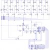
Regarding the 4029,
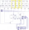
I was going to makes slots of different sizes so that each coin falls through the first slot it can. [See Attachment]
On the other side of the holes would be opto-isolators, which would detect and give an output when the IR connection is broken.
I would feed these outputs into a GENIE PIC, on which i would make a flowchart based on the input of the pin, giving out pulses. For example, if there was an output which from a 2p coin fed into an input of the PIC, i would make the flowchart give two pulses to count up for the 4029. This goes for all the coins.
Next, the reason i wanted the PTM switches was that if the user takes out some money, he/she can subtract from the total display. This is so it goes down.
To go up, i would need that in case they subtracted a bit too far.
That was my model specification of the circuit.
=]
Can you expand on the idea of the mechanism which detects coin diameters and weight please??
Regarding the 4029,
I was going to makes slots of different sizes so that each coin falls through the first slot it can. [See Attachment]
On the other side of the holes would be opto-isolators, which would detect and give an output when the IR connection is broken.
I would feed these outputs into a GENIE PIC, on which i would make a flowchart based on the input of the pin, giving out pulses. For example, if there was an output which from a 2p coin fed into an input of the PIC, i would make the flowchart give two pulses to count up for the 4029. This goes for all the coins.
Next, the reason i wanted the PTM switches was that if the user takes out some money, he/she can subtract from the total display. This is so it goes down.
To go up, i would need that in case they subtracted a bit too far.
That was my model specification of the circuit.
=]
")