I want a circuit that will count up from 0 to 9999.
This circuit will use a dual 7 segment display.
Also, i want it to count down at any point, for example, if the value is 30, it should go back to 29, then 28 etc.
I have done some research and know that the 4029 and 4511 will help me achieve this.
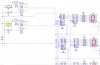
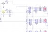
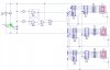
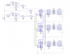
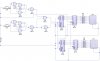
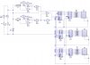
Attached is my circuit so far. It does the basic counting from 0-9 upwards and downwards.
How can i carry on from this circuit to make it count up and down using a dual 7 segment display, or two individual 7 segment displays?
Thanks a lot!!!
=]
This circuit will use a dual 7 segment display.
Also, i want it to count down at any point, for example, if the value is 30, it should go back to 29, then 28 etc.
I have done some research and know that the 4029 and 4511 will help me achieve this.
Attached is my circuit so far. It does the basic counting from 0-9 upwards and downwards.
How can i carry on from this circuit to make it count up and down using a dual 7 segment display, or two individual 7 segment displays?
Thanks a lot!!!
=]
")