Continue to Site

Welcome to our site!

Electro Tech is an online community (with over 170,000 members) who enjoy talking about and building electronic circuits, projects and gadgets. To participate you need to register. Registration is free. Click here to register now.

  • Welcome to our site! Electro Tech is an online community (with over 170,000 members) who enjoy talking about and building electronic circuits, projects and gadgets. To participate you need to register. Registration is free. Click here to register now.

Up/Down Counter Circuit

Status
Not open for further replies.
Hmm..

other than the GENIE PICs, which i can understand you have not much control on it, what do you recommend??
 
Hmm..

other than the GENIE PICs, which I can understand you have not much control on it, what do you recommend??

Your Geni PIC'S allthough for you look very good might just lead you away from more standard Microchip methods and thus people might find it difficult in helping you out.

Having taken a look at the Genie (and I agree with Eric about it being one of the worst sites ever) I see that each of their PIC's are based upon Microchip devices-

Genie C08 = 12F683
C14 = 16F684 and so on

This means they are common place PIC's and not specific to Geni.The only thing that will be different is the programming platform.
 
Hmm..

other than the GENIE PICs, which i can understand you have not much control on it, what do you recommend??

hi,
Add the two AND gates to CIN/Co as shown in this drawing.
 

Attachments

  • AAesp02.gif
    AAesp02.gif
    45.4 KB · Views: 548
I looked at the Geni package and it only works with flow charts and then it converts this to code direct to the PIC. (ON DEDICATED PROJECT BOARDS) You have no control over the actual code and cannot import code in to the software.

Having said that you have some PIC's available and project boards? I'm thinking that an .HEX file could be uploaded to a suitable PIC. via another platform using your project board as a programmer.. Eric might be able to confirm that better than I can.

What PIC's do you have again?
 
Last edited:
Hey,

Wombweller: GENIE PICs do not look good to me in this project. It just happens to be the ones that my software, Circuit Wizard, supports, and the one i have to use. Also, like you said, the only difference is the programming platform. In the perspective, they are all different chips then.

Eric: You going to hate this part.
It doesn't work!!

I have connected the AND gates to the circuit, and on the attachment, i have just coloured the rails so that it is easier for you to see the connections.

What is not working this time is the following:

For the units (for both count up and down)
0000,0101,0202,0303...0808,0909,1010,1111,1212,1313,1414 etc. [counts up in 101s]

For the tens
[Count Up] 0000,0011,0022,0033...0088,0099,0110,0121 etc [counts up in 11s]
[Count Down] [After Count Up Is Pressed] counts up in 1s
[Pressed Straight Away] counts up in 101s

For the hundreds
[Count Up] Counts up in 101s
[Count Down] Counts down in 1s.

I know this is really frustrating for you, but i appreciate every post of help.

Thanks a lot!!!!!

=]
 

Attachments

  • 6.jpg
    6.jpg
    97.1 KB · Views: 488
hi,
One point is you have not added an AND gate between the 100' and 1000's for starters, my circuit is shown for only 3 decades.

All the connections between 10 and 100 must be repeated for 100 to 1000
 
Last edited:
hi,
One point is you have not added an AND gate between the 100' and 1000's for starters, my circuit is shown for only 3 decades.

All the connections between 10 and 100 must be repeated for 100 to 1000

Hey,

Which section of my circuit will this additional AND gate connect to though??

Thanks

=]
 
Hey,

Which section of my circuit will this additional AND gate connect to though??

Thanks

=]

hi,
I would have thought could have worked out for yourself, how the additional gates for the 4th decade are connected.:rolleyes:

Its just a repeat of the 1,2 & 3rd decades, its now all in this last image.

I did tell you that the circuit would grow like topsy as you decided to add features to it.

I hope you have learned an important lesson when embarking on a project, do the paperwork project specification/proposal FIRST, which should include ALL the features the project NEEDS to function, BEFORE starting the design... and to resist adding features to the project as it progresses....:)
 

Attachments

  • AAesp01.gif
    AAesp01.gif
    46.6 KB · Views: 245
Hey,

I think you have misunderstood me.
Sorry about that.

I do not need the switch to count up and down for the 4th decade.
That should work as normal.

That is why i had asked you that.
 
Hey,

I think you have misunderstood me.
Sorry about that.

I do not need the switch to count up and down for the 4th decade.
That should work as normal.

That is why i had asked you that.

You have to have the clocks and the CIN/CO connected to the 4th decade using gates else you will get the problem you are seeing.!!!!!!!!!!!!!

EDIT:
Look at this image
 

Attachments

  • AAesp01.gif
    AAesp01.gif
    63.7 KB · Views: 277
Last edited:
Hey,

I am really sorry for the late reply.
I have been away recently.

Regarding my circuit,
Like you said, it has become to messy, but there are also features that i do not require in it that you have posted.

This is what i want it to do:

Count up and down in the first decade
ONLY UP in the second.
Count up in the third [down if possible but not necessary]
The fourth works as normal without manual inputs.

Can this be done?

Thanks

Those extra features you mention are required to make the circuit work, the 4029's are clocked as a synchronous up/down counters, so to clock any of the 4029's individually up or down, the inter 4029 gating circuits are required.

Run that complete last circuit I posted in simulation and see what you get.
 
hi,
Its not a bother, its more frustrating because we are not getting an agreed result, so let me explain what I think you are asking..:)

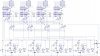
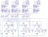
Assume that the counter is displaying 000
I press the units UP key 111 times, I expect the display to show '111'
pressing the units DOWN key 111 times I would expect to show '000'.

OK so far
Assume I have '888' displayed.
I press the units UP key once, so number displayed is 889

I press the tens UP key once I expect to see 899 displayed
I press the hunds UP key once I expect 999

OK,

I press the hunds DOWN key 9 times I will see 099
I press the tens DOWN key 9 times I will see 009
Pressing the units DOWN key 9 times I will see 000

Is this what you are expecting from the counter, if not please give a numeric description of what you want.???


Mastahh
Could you send me your schematic sim you have thus far.I have livewire made by the same company as Circuit Wizard (New Wave Concepts) but perhaps you ought to re-think your design to suit Eric's circuit.

One thing to remember in some Sim's is they don't always simulate as they would act in real life:confused: yes I realise this sounds a little stupid so I brought this up with New Wave concepts who suggested I update the software..still I get simulations that don't work as they should..the result is we think we have designed the circuit with errors.
 
Last edited:
Hey,

Maybe what wombweller is saying is true, considering both our sims are made by the same company.

Regardless of that, as an update... none of the switches are working.
The display starts at 0 and stays at 0.

Attached is my circuit. [Note: it is a big circuit and so may not be easy to see, as the size had to be reduced to fit the picture]

Thanks

=]
 

Attachments

  • 7.jpg
    7.jpg
    115 KB · Views: 299
Hey,

Maybe what wombweller is saying is true, considering both our sims are made by the same company.

Regardless of that, as an update... none of the switches are working.
The display starts at 0 and stays at 0.

Attached is my circuit. [Note: it is a big circuit and so may not be easy to see, as the size had to be reduced to fit the picture]

Thanks

=]

Post the file so I don't have to draw it all, I will simulate it on my PC.
 
Status
Not open for further replies.

Latest threads

New Articles From Microcontroller Tips

Back
Top