Continue to Site

Welcome to our site!

Electro Tech is an online community (with over 170,000 members) who enjoy talking about and building electronic circuits, projects and gadgets. To participate you need to register. Registration is free. Click here to register now.

  • Welcome to our site! Electro Tech is an online community (with over 170,000 members) who enjoy talking about and building electronic circuits, projects and gadgets. To participate you need to register. Registration is free. Click here to register now.

Ultrasonic Reciever unit idea

Status
Not open for further replies.

pigman

New Member
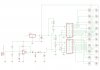
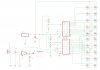
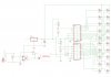
Hey guys, this is a bit of a strange one that I'm working on... I need to receive and ultrasonic waves using a small ultrasonic transducer like this Ultrasonic Transducer and then represent the signal strength and frequency (strength is more important) in either a bar of LED's or an LCD or something like that... All of the circuit examples I can find are for proximity sensors and whatnot and none really cover what I'm after.

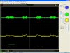
Using a DSO I can get voltages from the little transducer when in proximity to the signal I'm testing the strength of, could there be some way to use the varying voltage to give a graphical representation ? Any help or a shove in the right direction would be greatly appreciated.

Cheers
 
mmmh maybe using a filter considering wave as a sound signal always from above 16000, digital resampling is not usefull, (I've tried it with my dog... no results), maybe a filtered amplified mic-speaker circuit with pot adjustment will let you... remember ultrasonic waves are mollecular-based not electronic... the equation then derives from sound spectrum (harmonics) so recalibration for data transfer is needed
 
Possibly amplify the voltage from the transducer (you don't mention amplitudes) and drive a chip like the LM3914. That would give you a LED bar graph display proportional to the signal.

Ron
 
Relaodron, Your idea with the LM3914 is an interesting one! What chip could I use to amplify the signal? I haven't got any specific high and low readings as yet however I will get some hopefully tomorrow. One issue is that the signal from the Transducer would be an AC signal, so I suppose I would need to rectify that, then amplify, then read using the LM3914 to display on the bar graph?
 
Relaodron, Your idea with the LM3914 is an interesting one! What chip could I use to amplify the signal? I haven't got any specific high and low readings as yet however I will get some hopefully tomorrow. One issue is that the signal from the Transducer would be an AC signal, so I suppose I would need to rectify that, then amplify, then read using the LM3914 to display on the bar graph?


No you amplify it first, then rectify it - you can use pretty well any decent opamp as the amplifier, the Texas TL081 series or similar would be fine.
 
OK, What about something along these lines?

I'm not 100% on how to rectify it, and obviously no idea on voltages yet so every value (including how much to amplify it) is open for adjustment. I've added two LM3914's to give more resolution to the output and tied the low of the second to the high of the first, both with their own reference high's trimable (again trim values are open to change). The amp is a basic LM386 with a Amplifier Gain of 20 as per the doco.

Let me know your thoughts.

Cheers
 

Attachments

  • us-receiver.jpg
    us-receiver.jpg
    237.1 KB · Views: 237
Last edited:
OK, What about something along these lines?

I'm not 100% on how to rectify it, and obviously no idea on voltages yet so every value (including how much to amplify it) is open for adjustment. I've added two LM3914's to give more resolution to the output and tied the low of the second to the high of the first, both with their own reference high's trimable (again trim values are open to change). The amp is a basic LM386 with a Amplifier Gain of 20 as per the doco.

You don't use an LM386, that's a power amplifier - not an opamp.
 
ohh ok my bad, what about a LM741? I would go with the tl081 but I have a bunch of LM741's handy if that will work?
 
Ok, What about something like this? Updated with the LM741, I am not very used to using a LM741 for this purpose, so please let me know if the "gain boost" circuit I've done is suitable or will even work at all :| . Also what sort of rectifying do you think would be suitable here?

Thanks guys
 

Attachments

  • us-receiver2.jpg
    us-receiver2.jpg
    225.2 KB · Views: 225
Before we worry about amplification and rectification it would be wise to know what it is that we are going to amplify. You mentioned a DSO so when time allows take a good look at the signal you get from the transducer. Once you know what you have (in detail) then we can worry about amplification and rectification. While the 741 may work the op amps like the TL081 would be a much, much better choice. It offers a nice high impedance J FET input and if the transducer is typical low impedance out they could make a nice marriage. :)

Ron
 
Ron,
Thanks mate, yes I'll slap the US Transducer onto the DSO asap, I was just working in some spare time on a schematic to get started on this little project. I was messing around a while back with the signal from the US Transducer and it is an AC signal (receiving 40KHz from the main transmitting transducer) and at it's peak has enough juice to light two small leds (the where joined A to K of each other) when messing around. I'm not sure if this is enough information for you at this time?
Cheers
Josh
 
Ok, What about something like this? Updated with the LM741, I am not very used to using a LM741 for this purpose, so please let me know if the "gain boost" circuit I've done is suitable or will even work at all :| . Also what sort of rectifying do you think would be suitable here?

The 741 is an antique low-spec device, the main problems for this application are it's low input impedance, and it's low gain bandwidth. Your circuit also is compeltely wrong for wiring an opamp - try checking the opamp 'sticky' at the top of the General Electronics Chat forum.
 
wow, that is awesome. I've been googling all night and didn't find that one.

Ok so here is the latest, as I haven't got the specifics on the strength of the signal from the transducer as yet we can't be sure that this will all work as planned perfectly however it's a good starting point. What do you think? Any issues you can see here?
I will have to meassure the output voltages from the TL071 on the signal to figure out what the ranges should be set to on the LM391 chips and no doubt that will mean pot and resistor changes there, but other than that it all should work?

Cheers
 

Attachments

  • us-receiver3.jpg
    us-receiver3.jpg
    221.3 KB · Views: 224
wow, that is awesome. I've been googling all night and didn't find that one.

Nigel doesn't use Google, He uses some form of magic. :)

Per Nigel you can reduce the 1 Meg resistor to reduce gain. However, if you have a 1 Meg pot you could place it in series with a 1 K resistor then adjust the gain once you see how the transducer behaves.

Ron
 
The 741 opamp is 43 or 44 years old and was designed to operate ONLY from a plus and minis 15V supply (30V total). Yours has a 5V supply.
Your circuit operates near 40kHz but a 741 opamp has trouble above only 9kHz. Most good opamps work well up to 100kHz.
The input bias voltage of a 741 opamp must be near half its supply voltage but yours is at 0V where it will not work.
 
Hey guys, I produced the circuit and the op amp worked perfectly. Here is an output from the DSO Green is before op amp in AC yellow is after opamp in DC. I think I may need to increase the gain of the TL071, what is the highest it can go?
 

Attachments

  • us-transducer.jpg
    us-transducer.jpg
    141.6 KB · Views: 212
The gain of the opamp is set for 1M/1k= 1000 times.
The datasheet of the TL071 shows a typical max gain of a little less than 100 at 40kHz. Two opamps in series and each with a gain of 32 will have a total gain of 1024 times.
 
ahh, ok so a second TL071 will take it from 1000 times up to 1024 times? Sorry this is the first time I've used a TL071 chip, bit of a newb
 
Status
Not open for further replies.

Latest threads

Back
Top