Continue to Site

Welcome to our site!

Electro Tech is an online community (with over 170,000 members) who enjoy talking about and building electronic circuits, projects and gadgets. To participate you need to register. Registration is free. Click here to register now.

  • Welcome to our site! Electro Tech is an online community (with over 170,000 members) who enjoy talking about and building electronic circuits, projects and gadgets. To participate you need to register. Registration is free. Click here to register now.

OFF-the-wall idea for momentary ON switch

MrDEB

Well-Known Member
Looking to build a digital kitchen timer that shuts off after timing out and/or a 10 second delay waiting for user input.
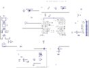
Here is the screenshot of the on/off section of the kitchen timer. Going to use an 18Fxxxx pic
maybe need a diode on the pic output pin to prevent applying voltage to the unpowered pic.
Screenshot (38).png
unpowered pic?
 
It's rather confusing what you're trying to do - but I presume it's to turn the PIC on from a momentary button press, and then have it time out and turn back off after a specific time.

This is commonly what I do on most of our products, using this small circuit:

The power button connects to pwr1 and pwr2, PL3 is a 9V battery feed. Q3 and R3 are there specifically to allow the push button to be used elsewhere in the programming, and to work as an off switch as well if required.

It's dead simple - pressing the button turns Q1 ON, powering the 5V regulator, and the PIC starts running - first thing it does is set RB0 high, to turn Q2 ON and maintain Q1 ON. Then after a predetermined time (if you want) the PIC can turn RBO low, and turn Q2/Q1 off, removing all power. If you press the button while it's running, Q3 turns ON, pulling RB1 low, and this can be used as an OFF switch if you wish, or as a general purpose button - I generally use it for as both.

PSU3.png


For a kitchen timer, you could use the button to set the required time, such as each press adds ten seconds.
 
Here is a flexible timer :


The blocks in right hand window you drag and drop out of second window which is function
blocks, and config. mBlock then converts that to Arduino code and programs the board or chip.
I ran this on low end 8 pin part, ATTINY85.

1703630984365.png


This generates pulses of user set width, and off time, and can trigger from a
pin state, or A/D value. Easy to add pulse width or frequency trigger.....


Regards, Dana.
 
Last edited:
I don't know which PIC you are using, so I looked at five 18xxx datasheets. All have a SLEEP mode, but thinking things through I don;t think you need it.

External switch - between the PIC GND pin and the circuit
External NPN or n-channel transistor - between PIC GND and circuit GND

Button press:

1. enter debounce software or whatever decision logic you need.
2. when conditions are met, one GPIO pin goes high, turning on the external transistor
3. do other stuff
4. When tasks are completed, drive GPIO pin low to disconnect the PIC GND from the circuit GND, turning off the device.

Or something like that.

ak
 
Last edited:
I think it can all be done in software with very little hardware circuitry - possibly just two resistors, two diodes and the switch. Just use the onboard timer, the enable pin or the sleep function.
 
This is just a bootstrap Set/Reset switch with a timer in between with two active transistors for the flop in the simplest Astable function.

The Set button triggers Pwr On and the uC sets a port to output high
by bootstrap method to drive the low side Pch switch to Vss (0V).

A Timer starts an output port high going and OFF into a high impedance state with an external pulldown resistor, to latch power off.

Parasitics help or may hurt the function and needs care.

But with sleep power being so low, why bother?
I think he also wants the switch to be functional as an input once the PIC wakes up so it needs a bit more than a simple bootstrap.

But I agree, the nanoWatt sleep on a PIC can, in theory, get years of service out of a small battery. However, actually getting years of service from a battery takes some level of understanding of how to shut down each peripheral and I/O setting of each pin.
The nanojoules of savings might be more than the uJ of charging every time the decoupling cap is charged up.. So better specs give better answers.

My free National Car Rental green ball timer/alarm from the 80's lasted for many years on a button cell with LCD clock.
 
Here's a collection of latch circuits I have collected over the years. #4, #5, and #6 would meet your needs. There are links to the original sources, which I suggest reviewing for details. The pdf is below.

Your schematic is illegible. Your unique use of the bus feature makes the schematic indecipherable. Busses are typically used to gather signals that have the same start and end points, such as the four port pins between micro and LCD. It's an express bus, not a local making stops everywhere.

I can't comment on your circuit because I can't decipher it, but I will note you need bypass caps.

[Corrected schematic for latch circuit #4, 1/3/24]

Click to expand, or download schematic below.
Argh. Somehow my numbers don't show up in the png images. #4 and #5 are the bottom two circuits on page 1, #6 is on page 2. The pdf does show the numbers correctly.


Schematic_Latching Power Switch Circuits_2024-01-03.png

Latch Circuits_2.png

mrdeb schematic.png
 

Attachments

  • Schematic_Latching Power Switch Circuits_2024-01-03.pdf
    116.6 KB · Views: 89
Last edited:
I viewed all the circuits from post #12. None have an ON/OFF delay.
Here is a revised schematic and a description of circuit

Pressing START starts the 10 – 15second delay (this section needs testing and adjustment)


The ON LED is enabled as well asturning the Mosfet ON thus turning ON the microprocessor.


The Mosfet is configured as a high sideswitch thus turning ON the microprocessor.


If portB has no input during the 10-15second time delay then the microprocessor turn OFF.
Screenshot (40).png
 
I viewed all the circuits from post #12. None have an ON/OFF delay

You'd think I'd learn my lesson by now. Sigh.

Circuits #4, #5 and #6 power up the micro for the period the button is pressed. The first and immediate thing the micro MUST DO is asset the power-on port pin to stay on after the button is released. Then the micro waits for some action, which in this case is one of the time buttons to be pressed. If this happens, the timer counts down, and the micro turns off the power-on port pin, shutting everything off.

If no timer button is pressed during whatever interval you desire, the micro shuts off the power-on port pin and everything is turned off.

I am certain the EEVBlog Dave explains this concept very clearly in the linked video.

Please note carefully that none of the timing functions will be amenable to using DELAY statements
 
And by the way, screen-shotting your schematic AGAIN still doesn't make it legible.. Do you even look at the stuff (not my first choice of words) you post to see if it's readable?

What I can see in your schematic is that the LCD has no ground connection, which doesn't much matter anyway since none of the control pins are connected. The backlight however is connected between +5 and ground, so it will always be on. It will be a nice nightlight, so all is not lost.
 
Last edited:
Squinting at the latest schematic, it looks like power is applied to the uC immediately when the button is pressed, through one driver transistor and one pass transistor. For that function, why not eliminate both transistors and simply ground the Vss pins through the switch.

To keep things running after the switch is released, put back the NPN transistor so that its collector and emitter are in parallel with the switch.

In the schematic, the button press initiates an R-C timer to hold the NPN control transistor on after the button is released. Again, this can be done inside the uC, which already has to have code to drive the uC pin 3.

ak
 
Last edited:

Latest threads

New Articles From Microcontroller Tips

Back
Top