Continue to Site

Welcome to our site!

Electro Tech is an online community (with over 170,000 members) who enjoy talking about and building electronic circuits, projects and gadgets. To participate you need to register. Registration is free. Click here to register now.

  • Welcome to our site! Electro Tech is an online community (with over 170,000 members) who enjoy talking about and building electronic circuits, projects and gadgets. To participate you need to register. Registration is free. Click here to register now.

Ultrasonic Reciever unit idea

Status
Not open for further replies.
ahh, ok so a second TL071 will take it from 1000 times up to 1024 times? Sorry this is the first time I've used a TL071 chip, bit of a newb
You don't understand.
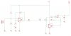
If you had a very high frequency opamp then the 1M and 1k resistors would make the gain 1000 times. But the max gain of a TL071 opamp at 40kHz is less than 100, about 85 times. So if you use two TL071 opamps in series (or a TL072 dual opamp) and each with resistors setting their gains at 32 times then their total gain at 40kHz will be 1024 times. Their maximum voltage swing will be 28V p-p.

An old 741 opamp has a max gain of only about 20 times at 40kHz and its maximum voltage swing will be only about 7V p-p.
 
Last edited:
Ahh, I get you, yes I was only thinking about the LM741 as I have a heap of them handy. But I have the TL071 chips now and they are working well. I have made some changes to the Bar Graph circuit, switching to the LM3915 and am going to try out the very basic "vibration sensor" from the chips doco. I will use the op amp to boost it once and raise the sensitivity of the LM3915. There is also a peak detector circuit using an LF351 (should substitute the TL071 fine there) that I'll be adding also given the duty cycle as you would have seen on the DSO screen grab.

I've removed the rectification as apparently it's not needed. Let me know if you see any flaws in this.
Cheers

*EDIT* the two Caps on the boost circuit are supposed to be 1N not 1uF
 

Attachments

  • us-transducer2.jpg
    us-transducer2.jpg
    78.2 KB · Views: 234
Last edited:
Your second TL071 (the rectifier) is not biased properly so it will not work.
The supply is only 5V but the minumum supply for a TL071 IS 7V.
 
Really? buggar, that circuit schematic is straight out of the tech doco from the LM3915. voltage I will just increase, no problem. What needs to change for the second TL071 to work? It is a peak detector for the LM3915 so it holds the peaks for a short period as they only exist for a limited amount of time (a couple of ms).

Cheers
 
Really? buggar, that circuit schematic is straight out of the tech doco from the LM3915. voltage I will just increase, no problem. What needs to change for the second TL071 to work? It is a peak detector for the LM3915 so it holds the peaks for a short period as they only exist for a limited amount of time (a couple of ms).

The circuit assumes that you know that most opamps using it need a dual-polarity supply but your supply is missing the negative voltage.
I designed a similar circuit as yours but I used a MC33171 or MC34071 single-supply opamp that works perfectly when its inputs are at the negative supply voltage which is 0V in this circuit.
Here is my circuit:
 

Attachments

  • preamp and peak detector.PNG
    preamp and peak detector.PNG
    26.6 KB · Views: 405
Oftentimes sound intensity is displayed using a logarithmic scale (e.g. dB) as it gives a more meaningful value when relating intensity to loudness; additionally it increases the dynamic range for a given/set output range.

While I'm not sure what the device is for or the distribution of the expected input intensities, but if for example distance is a factor in the measurement, even if the transducer provides a linear/proportional response to sound intensity, it will give an response inversely proportional to the square of the distance from the source. A log amp (done using a diode or transistor in the feedback loop) can still be useful to compress the dynamic range (and somewhat "linearise" the output - note term is used loosely) in this case.
 
Dougy, thanks for that mate. Yes I opted for a shift to the LM3915 pretty soon on after discovering the logarithmic output of it. Audioguru's boost and peak hold circuit above worked great, while the intensity of the output is still pretty low I manage to simply increase the sensitivity of the Lm3915 and it seems to be working ok.

thanks heaps for your help guys!
 
Status
Not open for further replies.

Latest threads

New Articles From Microcontroller Tips

Back
Top