Continue to Site

Welcome to our site!

Electro Tech is an online community (with over 170,000 members) who enjoy talking about and building electronic circuits, projects and gadgets. To participate you need to register. Registration is free. Click here to register now.

  • Welcome to our site! Electro Tech is an online community (with over 170,000 members) who enjoy talking about and building electronic circuits, projects and gadgets. To participate you need to register. Registration is free. Click here to register now.

Tuned LCR circuit for humidifier

Status
Not open for further replies.
when i was younger working in a TV shop, having a display room full of TV's all running used to drive me up the walls. the 15khz noise used to give me headaches all the time. of course the boss couldn't hear it, but i could he was always wondering why i took smoke breaks so often...

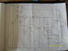
btw, antknee, i wish you wouldn't delete your posts like that, there's nothing now but my hastily scribbled copy of your schematic to work from. ... well there's the posted pdf's from others, but now nobody can follow the thread anymore from start to finish.
 
Last edited:
Hi Eric,

The Glade circuitry is a lot more complicated than a cursory glance makes it seem! I couldn't get the black epoxy blob off without damaging the board, shame. L2 is a transformer with a turns ratio of around 1:12 and C1 is a tiny microchip capacitor.If I remember correctly the piezo technology was developed by Pari a German atomiser company better known for medical nebulizers, I'm not sure how much of a hand they had in the electronics. I spoke to them and incidentally they had brought their technology to my former employer (an aerosol company) for evaluation, it was turned down.

The patent I want has the International Patent Classification B05B 17/06 - vibrating plates. The Glade has a vibrating plate, it is the mesh and piezo combined. The mesh is probably made via electrolysis from Invar, a nickel alloy. Steminc sell something similar. I have had in mind two patents both of which are similar, one my prefered and the other a backup. It does now occur to me that the electronics combined with a vibrating plate is patentable, its something to think about.

I'm going to get one of the Buzz Stain Removers. That looks interesting. Quite useful in fact! Thanks. I will have to absorb electronics for some time before the path I need becomes apparent.

My caps and opamps shipped in 12 hours. That was good. I bought resistors and inductors from another supplier, not heard from them yet.

I will have to get an audio transformer as you mentioned. I will look into it.

Thanks,

Antknee.
 
Hi Unclejed,

I bought some piezo tweeters a while back to take apart. They seemed to be a piezo diaphragm with a horn, I think these must have been a siren and what you were looking at is different.

I've got a lot of piezo electronics on the go now! Makes me happy though, I like a challenge!

I deleted my posts because I thought I was going to be offline for a long time and it would be mean to have people reply and not be able to reply to them. I should have just left them and I've uploaded a copy of the original circuit schematic, its a little different from Eric's but more or less complete.

Thanks,

Antknee.
 

Attachments

  • S6307065.JPG
    S6307065.JPG
    2.7 MB · Views: 685
Last edited:
Hi Antknee,
Not sure which one you seek but a full listing of US patents with International Classification B05B 17/06 is attached (96 results). These are hyperlinked to the US patent server. If you don't have a TIFF imager installed use Google patents and plug in the numbers to view.

The Buzz product is pretty interesting for $20. US. Includes power supply, drive circuitry and piezo horn (similar to ultrasonic welding horns).

Eric
 

Attachments

  • ICLB05B01706.doc
    314.5 KB · Views: 532
Last edited:
Hi Eric,

Thanks. I'd say you were very skilled at piezo work and patent analysis. Makes me wonder if you already have some patents. I like those Buzz Stain Removers. I had a look and one embodiment is mentioned as working at 50KHz. Which is in a good ball park for me.

I just bought an oscilloscope. Its nothing fancy but should be sufficient for my purposes. I'd have prefered a slightly higher frequency but 2MHz will be ok. Incidentally we had the gas man here to fix the boiler last week and he had exactly the same model.

**broken link removed**

I need to find an order to project work. Probably this:-

1) Alter compoents on the steminc 1.67 MHz circuit and 2.5MHz. Look for 133KHz.
2) Wire up the general purpose opamps and see how they work. Build a simple circuit.
3) Build neb2 or something similar.
4) Find out how to use the power opamp and build a circuit.

Can you think of any useful experiments to carry out? I'd like to split the tasks into smaller sub tasks.

Unclejed. If you were starting out with these tasks what would you be looking for?

Thanks,

Antknee.
 
Hi Antknee,
I'm an electrical engineer from way back and do much patent work today. Resonance phenomena have always been a keen interest of mine.
Good deal with the handheld scope. This is a required tool for oscillator work.

If you only want to energize the piezo element that you have inorder to investigate something then the Buzz could work for you.

If your interest is making your own circuit for a product application then build one from scratch with the parts you ordered. The neb3 circuit seems a very stable oscillator design to start with. Use a project breadboard to allow parts adjustments.
Build or buy a DC power supply that can provide the voltage and current required.

Build a simple 555 timer circuit to generate your signal. Run that through your audio amplifier chip (LM3886) and through an audio transformer to the piezo.

Eric
 
Hi Eric,

I will buy a Buzz. Energizing the pzt would be the simplest option. I am going to try and get the pzt ordered this week. I have had some quotes and the lead time for delivery is around 8 weeks, it will take another month or so to test and build the plate, so it will be a while before I can know whether the Buzz circuitry and my new atomiser would work definitely.

I will have plenty of time in the mean time. I will get the LM3886 chip working (hopefully) and have a go at building neb 3. I'm looking forward to this week, it is always good to have new things arrive and then have the satisfaction of making things work, even better if you have to work for it!

I started another thread asking about oscilloscopes. The consensus of opinion seemed to be buy a second hand one with lots of features. I thought about this, but with a new one at least I know it will work reliably. I was imagining testing circuits and scratching my head wondering why the numbers didn't add up. Only to find weeks later the oscilloscope needed calibrating! :)

Thanks,

Antknee.
 
I printed off a copy of the datasheet for my LM3886 chip and have been reading through that today. Its fairly complicated but I should be able to manage to use it. It does indeed want 1K ohm for Vin - and either 4 or 8ohms as a load/speakers. It does also have a problem with capacitive loads like piezo transducers. The method mentioned to counteract capacitive loading is to use an inductor in parallel with a resistor on the output. I cant work out whether this will be sufficient for the piezo or whether i'd need a second inductor in parallel Hmmm. For example if my piezo is 1.67MHz and I use a signal input of 1.67MHz sine wave what value or combination of inductor/resistance would I need. Hmmm.

I also have a feeling the impedance of my vibrating plate could be quite high, I'd guess 100 ohms.

There is a typical application in figure 1 of the datasheet which I can copy. Won't need the mute so I presume I can ground pin 8. Pins 2 and 11 have a notation "NC". I think that means no contact.

It will take me a few days to work out what I should do. Best get reading!

Antknee.
 

Attachments

  • DS011833.PDF
    434.2 KB · Views: 653
the LM3886 has definitely run out of gas at 1+Mhz. you can use it for 50-200khz piezo elements, but not 1Mhz.

you can transformer couple the piezo if the amp has problems with the capacitive load.

NC pins should be left open, don't connect them to anything. quite often they are internally connected to something, maybe for factory test purposes (like monitoring the output stage bias while the bias is being laser trimmed), but should never be tied to anything externally.
 
Hi Antknee,
Unclejed's right about not being able to drive the 1.67Mhz piezo with the LM3886. I thought your target was a 130Khz element?

Don't worry about the optional parts on the LM3886 datasheet. You will be running the amp through a transformer to match to the piezo, so the load will not be capacitive. I left only the essentials on the attached schematic. This circuit can drive your 130Khz element near resonance. The LM3886 will require a +/- power supply unless you wire it for single rail use and add a transistor to the circuit (see the datasheet for single supply wiring).

The 555 timer circuit is a useful oscillator. Use this page to calculate the resistance and capacitance values for the desired frequency:

555 Timer Oscillator Frequency Calculator

Eric
 

Attachments

  • 130Khz-piezo-drive.pdf
    39.6 KB · Views: 516
Last edited:
Hi Unclejed,

Thanks for the input, I'd forgotten I need the transformer, I started writing up part two of the notes from this thread last night but didn't get a chance to finish. My caps and opamps came this morning. The LM3886 is an impressive creature. The 2N3055 also arrived, I can remember seeing similar transisors in various household goods over the years, I'd always wondered what they were. Made me think of the 1960s sci fi show "The Invaders".

Hi Eric,

Thanks for the schematic. That's going to be very helpful :) I had a 555 timer before my recent move but I can't find it now. I will drop into the electronics store at lunch time and get one. I need to order the transformer I doubt the store will have that, but I'll ask. My target is 130KHz. I think I will supply the LM3886 with the 24V +/- and 0.8 amp supply I have, rather than a single rail use. The timer website is excellent. You do always have the best links. I'm impressed!

Thanks,

Antknee.
 
I did buy a 555 timer today. I was expecting it to cost a pound or two, it was 39p (60 cents). I was surprised and commented to the shop keeper peanuts cost more! I got it working on a breadboard with an LED at around 2Hz. All of my components came today so i've also been sorting those out into bins, i'm about half way through.

As I was doing this I looked around at my home office and realised it has become an electronics lab. I've worked in packaging labs and aerosol labs but never had my own. It does make me happy so I'm feeling quite upbeat :)

I think tomorrow night I'm going to change some of the components on the original board in this post to see if I can get it working at 130KHz. I have a feeling I'll fry the piezo very quickly but I bought a few so I won't mind losing one. I will also see if I can get the LM3886 working with some old speakers, or perhaps I'll see if a piezo buzzer/diaphragm will work, that might not be too capacitive. I will have to see what I can find and order that transformer.

Happy evening! :)

Antknee.
 
Hi Unclejed,

Thanks for the input, I'd forgotten I need the transformer, I started writing up part two of the notes from this thread last night but didn't get a chance to finish. My caps and opamps came this morning. The LM3886 is an impressive creature. The 2N3055 also arrived, I can remember seeing similar transisors in various household goods over the years, I'd always wondered what they were. Made me think of the 1960s sci fi show "The Invaders".

Hi Eric,

Thanks for the schematic. That's going to be very helpful :) I had a 555 timer before my recent move but I can't find it now. I will drop into the electronics store at lunch time and get one. I need to order the transformer I doubt the store will have that, but I'll ask. My target is 130KHz. I think I will supply the LM3886 with the 24V +/- and 0.8 amp supply I have, rather than a single rail use. The timer website is excellent. You do always have the best links. I'm impressed!

Thanks,

Antknee.

if you have some small toroid cores and some twisted pairs from Cat5 cable, you can wind your own transformer. the solid color wire for the primary, and the striped for the secondary. about 20-30 turns should be ok for 100khz or so. just wind the twisted pair through the core.

yeah, the TO-3 case might just have been the inspiration for the saucers in that show... i only caught one episode once in a while when i was young, but am now watching the whole series online now...
 
Hi Unclejed,

I have been looking to buy a 8:1000 transformer online but can't find one, there probably is one but I've not found it. I might have a go at building one, there is plenty of spare cat5e cable, that is ethernet cable if I recall correctly. I will have to get some cores, there will be a kit that will let me also create inductors.

I understand the logic of isolating the piezo from the LM3886 but the reason for the choice of transformer with this turns ratio and a 10uF capacitor eludes me. They are matching to impedance of 4 or 8 ohms I guess? I've been using this web page to get a handle on it so I can chose the right turns ratio and capacitor for other frequencies:-

http://www.geofex.com/Article_Folders/xformer_des/xformer.htm

My multimeter died last night. I don't think it liked trying to measure voltages at high frequency. It was measuring 3V DC at 1800V!

I used to watch The Invaders while growing up in the 1980s. It was on every saturday afternoon, the opening credits were very imposing and pulled you in. It is very good drama. I also liked the 1980s mini series "V".

Regards,

Antknee
 
Tonight I spent 3 hours working out how to use an oscilloscope. It's a very cool gadget! The new oscilloscope is pretty accurate, portable, durable and should do everything I want.

I was testing the circuit I started this post with. I was certain the transistor was rectifying the signal to half of a wave, I'm not sure why, but it is a full wave.

I was inputting 24V AC, across the piezo was 1.72MHz, 29.5V AC, with a high of +32V and low of -62V (around 100V peak to peak).

Eric, where is your piezo work up to?

Regards,

Antknee.
 

Attachments

  • g.JPG
    g.JPG
    318.6 KB · Views: 402
2 things about your meter.. DMM's don't like 1800V of anything. i've seen meters die from that kind of voltage, even as random spikes... second the AC voltage function is usually only good to a couple of khz, unless it's an audio True RMS meter, which is good to 100khz or so.
 
Hi Antknee,
Been enjoying your posts as you settle into your home office electronics lab. Fun stuff!

I've costed up a circuit based on neb1. It seems best for my application including water level detection shut off to protect the piezo and the lowest current draw. Depressingly, I found the complete neb1 assembly available for $10 US in quantity 1,000 from a China manufacturer. Have to buy from that region to get low cost piezo elements anyway....why not pick up the complete assembly...grrrr....:(

Attached is an improved neb1 schematic. Includes L2 (5mH on my board) and readily available actives.

Regarding your scope - amazing for the price. Yes, the piezo drive signal is a full sinewave. It rides above ground (never negative since supply is 0 - 36VDC). You can verify this on the scope.

Transformer: Find an old transistor radio (broken boom box, etc.). You will usually find an audio transformer in one of these.

Eric
 

Attachments

  • neb1a..pdf
    13.8 KB · Views: 586
don't count on a boom box having audio transformers. most of them were BTL (bridged transformerless) or single-ended capacitor coupled chip amps. and don't count on using the amp chips from boom boxes either, since those chips were mostly low quality amp chips that were already "out of gas" at 20khz.
 
Hi Unclejed,

The DMM measures that a voltage is present, so I can still use it for that purpose while I get another. I'm not sure why I persisted in trying to get a reading off it. I'll definitely make sure I don't do the same to my scope or LCR meter. I found some speakers in the garage which I will use while I decide what to do about the transformer. I'm not sure exactly which impedance they have, but they are satellite speakers so probably 4 ohms. I bought that pc hifi set, 7.1 speakers, with a new computer. I quickly realised they had more cabling than a small telephone company and I didn't need a personal eathquake device :)

I was going to get the LM3886 device up and running tonight, but found the pins don't fit in any bread or strip board I have. I will take it into the electronic store tomorrow and see what they have.

Regards,

Antknee.
 
Hi Eric,

Yes the office/lab is fun! It's amazing how stuff accumulates. I know in a few months I won't be able to move in there! :)

I think Western economies have trouble competing with Eastern economies on price. What the US and Europe have is plenty of clever engineers, designers and scientists. My oscilloscope says "Designed in Western Europe made in Taiwan". I'm aiming to create a water feature that looks fabulous and places it premium to anything else on the market, and is patentable. So I needn't worry about the cost of manufacture. Maybe you should design and patent some clever control electronics? If the electronics aren't a critical element, it is probably better to buy them in.

My scope won't measure the sine wave above zero, yet! There are a large number of settings and I haven't found exactly the right one. I also struggled with my power adapters, I'm going to have to buy something which will give me power reliably. I think most electrical engineers will have a device which will allow any voltage at the press of a button. Tomorow I'm going to alter the caps and inductors in the original circuit and see if I can get anywhere near 130KHz with enough power.

I'm eager to try and build neb1 or 2. It will be difficult I'm sure.

Regards,

Antknee.
 
Status
Not open for further replies.

Latest threads

New Articles From Microcontroller Tips

Back
Top