Continue to Site

Welcome to our site!

Electro Tech is an online community (with over 170,000 members) who enjoy talking about and building electronic circuits, projects and gadgets. To participate you need to register. Registration is free. Click here to register now.

  • Welcome to our site! Electro Tech is an online community (with over 170,000 members) who enjoy talking about and building electronic circuits, projects and gadgets. To participate you need to register. Registration is free. Click here to register now.

Tuned LCR circuit for humidifier

Status
Not open for further replies.
Hi Antknee,
Yes, the humidification is only one element and buying in that assembly now looks cheap enough to not warrant the effort. Your summary of the situation is quite right.

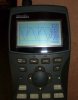
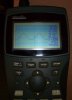
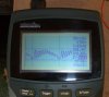
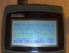
Put the scope in DC mode to see the off-set from ground of the signal.
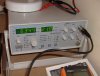
Yes, a good power supply is needed to run these circuits.

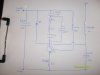
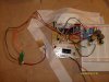
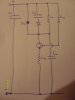
I would suggest getting some small alligator clips and solder those on wire stubs to the original circuit pcb where you remove the original Ls and Cs. Then you can quickly swap in parts until you get the circuit to resonate (watch the collector on the scope). Alternately you could run wires from those locations to a breadboard for the same easy/solderless parts substitutions.

Enjoy.
Eric
 
Hi Eric,

I took out C4, C5, C6, L1 and L3 and replaced them with wires. I fed those wires to a breadboard, on the board were components scaled up by around 16. I checked the cap and inductance of the values on the breadboard (inductors in series and caps in parallel) and then connected it all together. I replaced the atomiser leads with the 130KHz piezo atomiser.

C4 = 1.195uF
C5 = 273nF
C6 = 18.25nF
L1 = 753uH
L3 = 47uH

The piezo briefly buzzed and I got a voltage reading of 9V and I think 50Hz (could be wrong) and then the circuit died. I tested the piezo and it still buzzed happily in the audible range.

Could you think of anything I did wrong? I will put the circuit back together and see if it still works, but I don't think it will. I can keep the original piezo and will throw away the circuit board, but what about the components on the breadboard. How would I know if it was ok to keep any of the caps and inductors on the breadboard?

Tomorrow I will have a go at getting the LM3886 working! Hope I have more luck with that!

Regards,

Antknee.
 

Attachments

  • S6307140..JPG
    S6307140..JPG
    2.8 MB · Views: 683
  • S7303409.JPG
    S7303409.JPG
    3.2 MB · Views: 866
It occurs to me that this result was inevitable. Should I close down this avenue? I don't have enough experience of electronics to know whether this is likely to happen again, or have much idea what went wrong. I could make sure the circuit really is dead and if so buy some more. I did quite enjoy testing it :)

Regards,

Antknee.

Edit. I hadn't connected C6 properly and seem to have blown a fuse. Maybe the circuit has survived. Too tired for any more testing today.
 
Last edited:
Hi Antknee,
I'm visiting family a few states away right now so can not provide a proper answer. Will be back on Sunday. I would not expect a calculated component substitution to work on first try but rather you will need to tweek it to achieve resonance.

Since you are starting with the circuit shown in your S6307065.jpg, the transistor base biasing is through more resisors to V+ than shown in your latest sketch (I assume).

Enjoy,
Eric
 
Success!

Today i have had the circuit oscillating in line with what it should be. So i'm happy :D

I haven't changed anything on the breadboard from yesterday. I made sure C6 and everything else was connected properly.

The oscilloscope measures two different frequencies. Perhaps one is the tank frequency, I'm not sure.

The first is 54KHz at 40V peak to peak and the second is 42KHz at 20V peak to peak. I also measured the frequency with my signal generator, this came in at 63.5KHz. I was aiming for 130KHz and scaled the components accordingly.

Regards,

Antknee.
 

Attachments

  • S6307155..JPG
    S6307155..JPG
    171.7 KB · Views: 389
  • S6307153..JPG
    S6307153..JPG
    146 KB · Views: 368
  • S6307156..JPG
    S6307156..JPG
    290.2 KB · Views: 386
Hi Eric,

Thanks for your message! Enjoy your weekend. I hope it is a little warmer than snowy Wales :)

Regards,

Antknee.
 
Hi Antknee,

For now, cold snowy weather here on the east coast of US as well.

To your circuit: nice job with component values. The L1-C6 tank in the source of the 42Khz signal. The piezo isn't ringing though. Since the reactance of your piezo at resonance is <50 ohms and the original piezo ~2 ohms, I think your feedback current is too low to get the piezo to oscillate. Try increasing R15 to about 50 ohms to match the the piezo. Here is where parts swapping is useful. Again, keeping reactance/resistance ratios the same as the original, change C5 for a reactance at 130Khz of about 100 ohms (12nF). Make these changes stepwise noting the effect. Try R15 = 0, increase C6 to lower it's reactance, etc.

Increasing the start up to be closer to 130Khz would be helpful as well. 42Khz is about 32% of target while the original was 700/1666 = 42% (I measured about 800Khz or closer to 50% of target).

Increase base bias by decreasing R13 (currently 1K, drop to 330) or by decreasing the other bias resistors (R9, R10, VR).

Eric
 
Hi Eric,

Thanks for your message!

I did a number of things over the weekend. The first thing I did was to alter C5 from 273 to 600nF with the other components the same.

C4 = 1.195uF
C5 = 610nF
C6 = 18.25nF
L1 = 753uH
L3 = 47uH

This reduced the frequencies to 22.2KHz at 16.6V peak to peak and 15.3KHz at 40V pp

I then changed much of the frequencies on the board to these:

• C4 – 1.368uF
• C5 – 610nF
• C6 – 19.3nF
• L1 – 815uH
• L3 – 58uH

I coudln't get this one to oscillate at all and wondered if I'd missed a connection or the values weren't quite right. So I then put the original components back on the breadboard and connected them to the leads.

My original values as noted on the component markings (they measure a little different) are:

C4 - 0.1uF
C5 - 47nF
C6 - 1.5nF
L1 - 60uH
L3 - 4.5uH (2 turns of 18AWG at 7mm diameter)

It was hard for me to get any readings, my oscilloscope isn't rated to go above 2MHz. I did manage to get 2.5MHz at 15V pp. I have thought that perhaps the leads have reduced the the capacitance or inductance of the circuit. But it is hard to see how exactly.

I have also been trying to find an audio transformer that is 8ohm to 1Kohm. The Radioshack one below is ideal but they won't export. I found two UK companies that sell the same Radioshack brand audio transformer but they are both out of stock.

Audio Output Transformer - RadioShack.com

I think I need a turns ratio of 1:10, I found the transformer below which is 4 or 6 ohms and 320ohm.

NF-Übertrager 1:10

I bought the audio transformer below to have a look at. It is primary 1.2Kohm and secondary 3.2ohm.

**broken link removed**

Unfortunately it is rated at 0.2Watts so a little underpowered. I've been wondering if I can simply switch the primary and secondary. I will find some experiments to do with transformers, I need to understand them a little better.

Tonight I will put the component values back to those I first tried, which should still work, and follow your advice :)

Thanks,

Antknee.
 
Hi Eric,

I have spent 3-4 hours on this today but didn't make as much progress as I'd have liked.

I put the circuit back to these values (all measured):-

C4 = 1.18uF
C5 = 220nF
C6 = 16.9nF
L1 = 710uH
L3 = 50uH

The waveform I got was fairly unusual, see pic, it looked like a modulated signal. The first wavelength was 3.6KHz at 100Vpp and on this were smaller spikes at 48KHz and 15Vpp. I found that after a few seconds this circuit turned itself off, and i had to restart it.

I put C6 up to 19.1nF but it wouldn't start at all.

I then decided to try to scale all of the values a little more accurately but couldn't get the circuit started with those values either.

I then tried to think what is different today from yesterday. I think arrgh...if I recall correctly I was using a slightly different piezo. When I couldn't get the original circuit to work with the 130KHz, 50ohm, 2800pF piezo I switched to a similar one at 133KHz, 100ohm, 2000pF. I'm thinking perhaps this had a bigger effect than I'd imagined it would! It also occured to me that perhaps I didn't solder the wires for R15 properly. I wrote down the exact values I used for the original circuit, for example L1 was 680 + 47 + 22nF. So tomorrow it is the same again. I will check all these things.

The circuit I had working at 40KHz popped quite a few fuses. I remember being worried I would burn out the board. There wasn't much chance of that tonight :)

Have a good evening,

Antknee.
 

Attachments

  • S6307201..JPG
    S6307201..JPG
    104 KB · Views: 378
Hello Antknee,
I can't comment on your latest work. I'd suggest getting back to your original components. You can watch the supply current with your DMM in current mode and find out why the fuses are popping. A DC supply with at least 1.5 amperes looks necessary on this side.

Yes, transformers can be run either way. The audio transformer you have could work. Connect the 1K end to the piezo.

My piezo work is on hold for now as other items require my attention. Next month I will be overseas for several weeks but should still have web access.

Best regards,
Eric
 
Hi Eric,

I think I nearly have it now. I've spent a couple of nights learning the circuit from a practical point of view, it is interesting to see the theory come to life!

I haven't finished going through your last suggestions and I forget how many component changes I've been through, but a lot! I even got the piezo oscillating on two occasions at 121KHz but that was something of a mirage.

I can consistently get both piezos to run at the tank frequency, the one at 2000pF runs every time. I took R15 off and it wont run much above 7ohms, shorting it out stops the tank circuit. I changed C5, C6, L1, L3 stepwise but individually it made no difference. I increased the tank frequency up to 62KHz but still no luck. I have just soldered some leads into R13. My thought is that this will work and probably there just wasn't enough current. We'll see :)

You have been very helpful, thank you. And I have enjoyed the electronics and your input, it has been a great motivation. I have plenty to keep me busy, perhaps too much :) I will post updates to this thread occasionaly.

Thanks and I hope you enjoy your time overseas,

Antknee.
 
I did it! * Big grin * :D

It oscillates at 108KHz with 200V peak to peak and even atomises. I'm so chuffed!

The original circuit worked with R15 at 100ohm and C5 at 200 ohm impedance. I had to try it a few times more.

The tank frequency of 42KHz is L1 at 750uH and C6 (18.2nF) in parallel with the piezo combo (0.9nF).

The resonant frequency is C6 + piezo combo (19.1nF) with L3 (43uH) + implied inductance of piezo (70uH). The implied inductance looks too high and the resistor in parallel with the piezo would have dragged down the frequency, I will come back to this.

I'm going to have a go at the LM3886 for a few days, should be interesting :)
 

Attachments

  • S6307260..JPG
    S6307260..JPG
    75.8 KB · Views: 377
nice sine wave... looks like resonance to me...

it would be difficult to actually find the values of the "implied" inductance and capacitance of the series resonant circuit that is "seen" by the oscillator. these two values are electrical equivalents of the physical characteristics of the crystal. the 0.9nf you measure across the crystal is the actual contact capacitance, and is the parallel capacitor in the equivalent circuit of a crystal which looks something like this:
xtal-equiv..jpg

Rm, Lm, and Cm are characteristics determined by mechanical parameters of the crystal, and are the series resonant portion of the crystal. Rct and Cct are the contact resistance and capacitance. when you measure the capacitance of the crystal (assuming you are far from the resonant frequency when you do so), you are measuring Cct. Cct lowers the resonant frequency, but usually not by much.
 
Hi Unclejed,

It is good to succeed at a task. I dont think there is ever an endpoint as such, there are always improvements that can be made. But I enjoyed this milestone. Thanks for your input.

I'm finding the resonances hard to understand. I've uploaded a schematic of the circuit I have, the values have been checked and the frequencies are reproduceable. The tank frequency is 42KHz and the resonant frequency 108KHz. The piezo came with a datasheet, it notes resonance at 133KHz, impedance of 100 ohms and a Cct of 2nF.

I'm trying to understand how to calculate the tank and resonant frequency. Post #49 of this thread gives an indication.

I calculated the tank circuit frequency as:

The series combination of Cct (2nF), C4 (1.22uF), C5 (6.8nF) = 0.9nF

To this I added C6 in parallel = 18.2nF + 0.9nF = 19.1nF

L3 (750uH) x 19.1nF = 42KHz

To calculate the resonanct frequency of the board:

L3 (43uH) + implied inductance (70uH) = 113uH

19.1nF x 113uH = 108KHz.

Regards,

Antknee.
 

Attachments

  • schematic..JPG
    schematic..JPG
    246.4 KB · Views: 782
Last edited:
reducing C4 will raise the resonant frequency.
 
Hi Unclejed,

Yes it does. Thanks. I'm trying to get the LM3886 working, I thought I understood the pins but realised I don't! It isn't working, I'm having a problem understanding the difference between ground and V-, so I don't know where the pins are supposed to go. For example I'll be using a signal generator as the input. Vin+ is pin 10, Vin- is pin 9. So i connect the red lead of the singal generator to the Vin+ input, it goes through a variable resistor and 1Kohm resistor to get there. The black lead of the signal generator goes to where exactly? Ground or V-? I'm sure they are different as |Ground| - |V-| is meant to be over 9V from the datasheet notes.

I will make a new post to ask about that.

Regards,

Antknee.
 
Hi I am also trying to do a similar project
I am not expert in electronics but can manage myself
I am using a piezo crystal of the foll specifications for my humidifier application
Resonant frequency fr: 133 KHz±2%
Resonant impedance Zm: ≤100 ΩStatic capacitance Cs: 2000pF±15%@1kHz

Can someone suggest me suitable circuit for the same

Thanks very mush for any help
 
All. I'm looking for a basic driver circuit for a 1.6MHz piezo device in an atomiser/humidifier set up.
Iys been so long since I did any circuit design, its all a distant memory. But there are a few designs
through this thread that may suit my need, but as the general discussion is how to modify away
from 1.6, I'm not sure which to use - if any. Any help please?
 
i think the ones in post #62 or #67 will work for you. if antknee hadn't deleted so many of his earlier posts, there probably would be a few more...
 
Status
Not open for further replies.

Latest threads

New Articles From Microcontroller Tips

Back
Top