Continue to Site

Welcome to our site!

Electro Tech is an online community (with over 170,000 members) who enjoy talking about and building electronic circuits, projects and gadgets. To participate you need to register. Registration is free. Click here to register now.

  • Welcome to our site! Electro Tech is an online community (with over 170,000 members) who enjoy talking about and building electronic circuits, projects and gadgets. To participate you need to register. Registration is free. Click here to register now.

Protection circuit for 3 phase bridge misconnection?

Flyback

Well-Known Member
Hi,
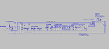
The attached circuit is the "standard" way to protect
against accidental misconnection of the 3 phase half wave diode bridge.
(ie a phase and neutral getting accidentally swapped)
But as can be seen, its a huge amount of componentry.
Any lower_component_count ways?

(LTspice and PNG attached)
 

Attachments

  • 3 phase diode bridge protection.png
    3 phase diode bridge protection.png
    52.3 KB · Views: 74
  • 3 diode bridge protection.asc
    24.3 KB · Views: 51
I would use a microcontroller.

Each phase would be connected with a potential divider, but a three-resistor potential divider. There would be a low value resistor between the analog input and ground, and an equal resistor between the analog input and +5 V (assuming a 5 V supplied microcontroller). The final resistor would be a high value resistor between the phase and the analog input. A total of 9 resistors for 3 phases.

So each phase would be measured, the peak negative voltage giving near 0 V on the analog input of the microcontroller, and the peak positive voltage giving near 5 V on the analog input.

With that, the processor can work out if all the voltages are correct and if the phase rotation is correct.

I did something very similar to check phase rotation using a PIC16F877 about 20 years ago. In that case the processor had to do a load of other stuff which is why I used a microcontroller with so many pins. There are 8 pin microcontrollers with 5 analog channels that could do what you want.
 
So each phase would be measured, the peak negative voltage giving near 0 V on the analog input of the microcontroller, and the peak positive voltage giving near 5 V on the analog input.
Thanks, the phases are each 90-265VAC....(each will be same voltage but anywhere between 90-265VAC).
.......Sorry i dont know why it put my words in quotes.
 
If you are allowing for the one of the phases to be swapped with neutral, the measured voltage could be up to about 650 V peak, the peak voltage between phases on a 3 phase 265 V system. That just means that you need a high-value resistor in the potential divider. 90 Vac signals connected correctly will be a bit small but the voltage will still be about 20% of the range of the ADC.
 
Hi,
The attached circuit is the "standard" way to protect
against accidental misconnection of the 3 phase half wave diode bridge.
(ie a phase and neutral getting accidentally swapped)
But as can be seen, its a huge amount of componentry.
Any lower_component_count ways?

(LTspice and PNG attached)
The way a lot of power electronics is done that involves connections that are not right is the connections are tested BEFORE any connection is actually made.

In other words, the phases and rotations are checked before the power is connected, in this case to the bridge.
This would involve a heavy duty switch in some cases. the switch is open for the test, and only after the test indicates the phases are correct, then the switch is closed.

I suppose you can make this automatic by using a contactor and measuring circuits, and a delay. First the measurements are made, then a decision is made to either close the contactor or leave it open and warn the user, then possibly close the contactor. If the only problem that can come up is the exchange of one of the phases and the neutral wire, then you can probably get away with measuring all the voltages and use a delay that is long enough to get the proper measurements. If you need to detect phase rotation then the measurement circuits have to be upgrade.
Note that it would be better to use a three phase contactor BEFORE the bridge not a single relay after the bridge.

Add some fuses and it should be ok.
 

Latest threads

New Articles From Microcontroller Tips

Back
Top