Continue to Site

Welcome to our site!

Electro Tech is an online community (with over 170,000 members) who enjoy talking about and building electronic circuits, projects and gadgets. To participate you need to register. Registration is free. Click here to register now.

  • Welcome to our site! Electro Tech is an online community (with over 170,000 members) who enjoy talking about and building electronic circuits, projects and gadgets. To participate you need to register. Registration is free. Click here to register now.

Tuned LCR circuit for humidifier

Status
Not open for further replies.
Hi Unclejed,

Yes I have other thought this one! I do that quite often! I will write up the scaling list and send for the components I need. I haven't done any electronics since school.

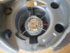
I cooked one of my atomisers earlier. If they get too hot they depolarise and stop working, I shall have to be careful not to let that happen again!

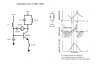
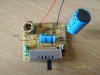
I reckon I probably don't need a tank circuit for these frequencies and I'd prefer a full wave rather than half wave. If the circuit doesn't work I'll move into investigating those.

Regards,

Antknee.
 
Here's another nebulizer circuit that runs at 1.67Mhz. Quite different arrangement.
From a low cost China humidifier.
 

Attachments

  • neb2.pdf
    10.6 KB · Views: 1,187
Hi eric,

I might have a go at building that, it will take several weeks probably. After this I will investigate building/adapting a high frequency amplifier. I could take a signal from a signal generator, amplify it times 10 and add the inductor/capacitance for resonance.

I actually want to patent a particular atomiser, I was working with something in my previous job. The atomiser won't of course work without the right circuit, so i don't actually have to have a circuit board, i need a means of demonstrating the atomiser and tuning the frequency to whatever I wish.

I took apart the fogger I bought last night. I dont think it was a piezo, the circuit is actually in the power adapter, it sends the power to the spring and the spring is in contact with a brass plate, see pics. I was a little surprised that the circuit was in the power adapter, because I used the same adapter with the board we've been looking at. And it worked! When I get a chance I'll take apart the power adapter and see what is going on.

Regards,

Antknee.
 

Attachments

  • S6306999.JPG
    S6306999.JPG
    2.6 MB · Views: 779
  • S6307000.JPG
    S6307000.JPG
    2.7 MB · Views: 670
using an oscillator and an amplifier is very similar to the method used by medical ultrasound scanners. in ultrasound scanners a gated oscillator is used to create a short "ping" much like a sonar ping, and then the return echoes are processed into a picture. a medical ultrasound uses power op amps that have the voltage handling and bandwith capabilities required for piezo transducers. something like this:
**broken link removed**

**broken link removed**

actually that company makes a few different amps, some of them specifically for driving piezo transducers. since you want a gain of 10 in your amp, use a device that has a gain-bandwidth product of at least 10X the highest frequency you plan on using. also look at the maximum load capacitance the amp can handle. piezo transducers are primarily capacitive, and an op amp with too much capacitance in the load is an oscillator (for a very short time before it burns up).
 
Last edited:
Hi Unclejed,

I was sure op amps couldn't do that! How did you know they could?! Thanks. One of those would make life a lot easier. The specs are also fine, I need at most +/- 100V and 0.1 Amps and 100KHz - 350KHz. I'd need to come back to the capacitance but I don't think that will be a problem. The piezos i think act like an inductor despite being capacitive, having written that tho it doesn't make much sense. Hmmm, yes must check that for sure.

The price of the PA85 is a little on the large side, £250 ($400) each new. I will search for something cheaper, i'm sure there will be something, or there's ebay, its quite possible i'd fry it while working out how it works. At times like this I regret just chucking out radios, tv's and other gear.

Thanks,

Antknee.
 
Here is the original circuit drawn out neatly. I wanted to understand the base bias circuit better. When the water level float is up the first transistor is off allowing the base current supply transistor to turn on.

Antknee,
I too will be building one up from scratch. The device you show could be a piezo element. Can you measure capacitance of it?

Eric
 

Attachments

  • neb1.pdf
    13.7 KB · Views: 892
Hi Eric,

The brass plate is a piezo after all. It had a capacitance of 1.7nF. I spent half hour sawing through the fogger 'block'. It was stainless steel case filled with a heavy plastic that had been poured in. I was expecting to find a circuit board and there was just wires for the LED, water level sensor and piezo element. The spring was there to increase the amplitude of vibration I presume. I've never taken a fogger apart, all seems fairly obvious now though!

I'm looking to build an air freshener rather than fogger. The drive circuits are similar but I wouldn't need to have a water level sensor for example and ideally i'd like full wave because I wish the pzt to contract as well as expand. I have designed the piezo atomiser and building that shouldn't be too much of a problem (we'll see). It is a work in progress and might take me the rest of this year.

When you've decided which circuit you are going to build let me know and I will have a go at building it on a breadboard.

I'm going to get back to making the list of components I need for scaling these two humidifiers and looking for a cheap power op amp. I have no components at the moment.

Regards,

Antknee.
 
Hi Antknee,
Yes, I thought it was a piezo. Searched around for JR410 (marking code) but came up empty handed. I bought a 2N3055 transistor at Radio Shack. Any equivalent NPN power transistor will work. I'm working on both circuits but will start with neb2. The lower voltage requirement is an advantage. For the voltage and current requirements of this oscillator I prefer the single transistor circuits over opamps.

Regarding your fogger - the circuitry will be in the power supply block. It makes sense that the drive circuit for the piezo could power up your second circuit (acted as a power supply when the piezo was removed). Spring is likely the electrical contact for one side of piezo button cell and frame the other.

Best regards,
Eric
 
Hi Eric,

I will look to build my device with transitors and opamps, both are a learning opportunity. I will order the parts for neb2, which VR range would be best?

For my fogger the spring was an electrical contact and the frame the other. I'm looking forward to taking the block apart and having a look tomorrow. I will have to make sure I don't damage it, I'm sure it will be useful again.

Regards,

Antknee.
 
Hi Unclejed,

I just read up on "gain bandwidth product". I guess I'd need a bandwidth of 2MHz for an op-amp at a voltage gain of times 10, up to 200KHz should be fine. I'm going to buy some op-amps and npn transistors to get going so I can better understand them.

Ordering L and C components is time consuming. Its one or two at this value and then another one or two at that and I'll have to put some in series or parallel to get the exact values I'd like.

I have a number of distinct routes to get where I need to be. Adapt the circuit I came to the forum, use an opamp, build neb2, build an npn circuit from scratch. It's just as well I enjoy this kind of thing! I almost studied electronic engineering at college, ended up doing physics instead.

Regards,

Antknee.
 
a standard op amp won't get the drive levels you need for those crystals. that transistor in the circuit is rated at much higher voltage and current than you'll get out of an op amp, and you need a lot of voltage swing to drive the piezo. i would say at a minimum you need an op amp capable of +/- 50V swing (remember with a power supply rail of only 36V, the voltage swing across the piezo is over 100V). and your standard op amp can only source or sink a maximum of about 10mA. did you price the PA107?. i don't know the power bandwidth offhand, but you might want to look at using something along the lines of the LM3886, which is an 85W audio power op amp (not to be confused with the LM386 which is a 1 watt chip)-------------

just looked it up.. GBW of the LM3886 is between 2 and 8Mhz (2Mhz is the guaranteed minimum, 8Mhz is what production samples average out at). the full power bandwidth is shown as 100Khz, but at 200Khz, there's still a lot of useable power there. the LM3886 will need to have a low value coil (25uH or so) to isolate the capacitance of the piezo from the amp output. oh, did i mention that the LM3886 is only $7.50 (US) or so? (i looked up the PA107, it's $360.00 (US))
 
Last edited:
Hi Antknee,
Physics is useful. :)

Regarding the value of VR =5K ohms.
Parts - it's good to have an assortment of resistor and capacitor values. Buy the kits with full ranges and sort them into bins.
I bought one of inductors a few years ago and have been building from that supply. But there are specific value combinations that will allow your circuit to oscillate (or so I have been finding). So there is a need for specific inductors. With an LCR meter to check ones work, these can be made. Here's a good online calculator for winding your own air core coils - Air Core Inductor Calculator.

Here's a source of inductor kits from Coilcraft. **broken link removed**
There appears to be many sources of parts kits on ebay at lower costs.

Regarding piezo air fresheners - here are some of the patents held by SC Johnson. These are the disposable ones sold under the "Glade" name. Quite impressive control circuitry!

**broken link removed**

**broken link removed**

**broken link removed**

**broken link removed**

Eric
 
Hi Antknee,

Succeeded in building a working oscillator from parts this evening. Attached is the schematic. Theory is from a nebulizer patent - optimal mist generation occurs when the piezo is operated at a frequency where its reactance is inductive. The tank circuit (parallel LC) resonates at about 1Mhz.

This circuit requires a hefty power supply (current was 1.5A).

Eric
 

Attachments

  • neb3.JPG
    neb3.JPG
    44.6 KB · Views: 3,398
Hi Unclejed,

I just bought the LM3886. An audio amp should be fine at <200KHz. I also bought a few general purpose 10mA opamps. I can learn how to wire opamps with those on a breadboard and not have to worry about larger voltages, note to self, must get the datasheet for them... I also bought a variety of capacitors and inductors, i picked them individually, wont be doing that again! lol The LM3886 was £4.40, about $7.50, looks good value to me.

Have you ever had cause to build or research piezo circuits in particular?

Thanks,

Antknee.
 
Last edited:
Hi Eric,

I bought a variety of inductor values. I have been googling for a site that will give me the right gauge and number of turns but didn't find a site as good as that. I'm pretty sure I will have to buy a kit and make some coils myself, particularly for low values. Thanks for the links.

I wish I could build a resonator circuit in a night! It is interesting that the optimal frequency for mist generation is above Fr. I hadn't considered that. Have you looked at how resisotrs in parallel to the piezo reduce Fr? I'm fairly sure I read that they do that, but this doesn't happen with resistors in series. What power consumption do you wish to have?

I have taken some pics of what I know as the Glade 'Wisp', it has a derivative called the Glade 'Candle'. It is the only air freshener that uses a piezo element (that I know of). I haven't mapped the schematic of the circuit but it is probably one of those that has been patented. It looks very simple, with a single AA battery sending charge to a 3300uF electrolytic, it charges at various lenghts of time dependant on the slide switch, potentiomenter. The resonant circuit is the toroidal inductor with a 47uF electrolytic. There is a transistor on the reverse of the circuit board probably rectifying the voltage. There are also a couple of chokes and a diode and that seems to be it! It is a little low powered for me but for simplicity it gets plenty of marks.

Regards,

Antknee.
 

Attachments

  • S6307039.JPG
    S6307039.JPG
    2.7 MB · Views: 762
  • 63.JPG
    63.JPG
    310.3 KB · Views: 1,271
  • 4.JPG
    4.JPG
    364 KB · Views: 1,594
  • 47.JPG
    47.JPG
    310.3 KB · Views: 1,176
  • 3.JPG
    3.JPG
    350.1 KB · Views: 3,194
Last edited:
Hi Antknee,
1. Your Glade - Yes, the epoxy blob top marked U1 is the IC and the heart of the circuit as described in the patents.
2. Yes, there are patents on the candle version as well.
3. LM3886 - I've used this audio amplifier in the past to drive piezo elements. It will work fine. You will need an audio transformer to couple the piezo to the LM3886 output as it expects 4-8 ohm speakers. Radio Shack sells one that works fine (8 ohm one end, 1K ohm the other). For that matter I have used an old stereo amplifier and the transformer to drive piezos with a signal generator.
4. LM3886 - There is a product called "Tide Buzz" that uses this IC to drive a piezo transducer in order to clean stains from clothes. Sort of a hand held ultrasonic cleaner. I've studied this design in the past when I needed localized ultrasonic energy for a specific application. Here is a link:
Tide Buzz Stain Remover Powered by Black & Decker

**broken link removed**

Eric
 
i've tinkered with ultrasonic oscillators and "super-tweeters" a long time ago as a theft deterrent device for storage spaces. i built a device that emitted a 120db ultrasonic (22khz) tone that would cause headaches, and was triggered by a tripwire switch. i was going to mention earlier, that the tranducers you killed are most likely fractured internally and that's why they no longer work. when they're operated at their resonant frequency, they tend to generate large voltage spikes (one of the reasons for the shunt diode by the way), which can get high enough to discharge across the electrodes and fracture the ceramic. i did it plenty of times with the ceramic diaphragms of the super tweeters. after the ceramic fractures you then have 2 or more portions of the crystal with resonant frequencies much different than the original crystal. the existence of the air gap reduces the maximum voltage of the device to very low voltages.
 
Last edited:
Hi Unclejed,
When I was younger I had "dog" hearing and ultrasonic security systems really bothered me. It seemed like they were 120db!
My replacement piezos arrived today! I'm using the tank part of a humidifier to keep the piezos cool now.

Antknee,
The piezo driver on your Glade is a power MOSFET from On Semiconductor. Here is the data sheet:

NTF3055L108

Eric
 
Status
Not open for further replies.

Latest threads

New Articles From Microcontroller Tips

Back
Top