Continue to Site

Welcome to our site!

Electro Tech is an online community (with over 170,000 members) who enjoy talking about and building electronic circuits, projects and gadgets. To participate you need to register. Registration is free. Click here to register now.

  • Welcome to our site! Electro Tech is an online community (with over 170,000 members) who enjoy talking about and building electronic circuits, projects and gadgets. To participate you need to register. Registration is free. Click here to register now.

taking a percentage of 2 counters

Status
Not open for further replies.

rafi21

New Member
Im designing a project and im a little stumped on one feature i want to implement.
how can i take a percentage of 2 counter ICs? or even more elaborated, cascaded counters.
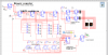
im using 74LS192 BCD counters and 74LS85 i believe is the binary comparator.

so how can i take counter#1 and check if it is 75% or higher out of counter#2?


and another problem i had was that counter#2 would always be 3 or 4 counts or clocks ahead of counter#1 because the way my circuit was designed.
i did think of taking NOR/AND gates to give a reset to counter#2 by checking if the inputs are 0000,0000,0011 (3 digit bcd) but just wondering if there was an easier way without all those zeros(so it doesnt reset on 13,103, etc..)

also some side questions, is there a chip that combines BCD counter with 7447 display driver into one chip?

thanks
 
Do you mean specifically that some output should be high if the value in counter A is > X% of the value in counter B and low if A <= X% of B ?

If not please explain exactly what you want.

It would also help if you explain how the values in counters A and B are updated - especially whether there is a major time difference. For example does A only change occasionally and B frequently? And how accurate does the comparison have to be - this would have a bearing on the need for synchronicity (is that a word?) between the counters.

Does the percentage need to change or is it fixed? If it changes how does that happen, how often and between what limits?
 
is there a chip that combines BCD counter with 7447 display driver into one chip?
Don't think so. The CD40110B combines a decimal counter and decoder. But that chip only outputs the segment bits, not the count value, so won't be of use (without a lot of complex logic) for comparing count values.
and another problem i had was that counter#2 would always be 3 or 4 counts or clocks ahead of counter#1 because the way my circuit was designed.
If the two counters are counting different things one will always be ahead of the other. So where's the problem? Do you want to synchronise the counts at some point (e.g. reset both to 0 simultaneously)?
 
Last edited:
How about,
Code:
BCD1->DAC->1/1 OpAmp\
                     > Comparator
BCD2->DAC->3/4 OpAmp/
I don't understand what you mean by a delay and have no idea what to do about it.

Or, just use a microcontroller.

Mike.
 
I don't understand what you mean by a delay
Who mentioned a delay?
 
Hello,

Another way is to use two preset down counters one as the reference counter and one as the comparison counter, and load counter 1 into one the reference counter and load counter 2 into the comparison counter, then run the reference counter at 10 MHz and run the comparison counter at 13.333MHz, and digitally detect a 'borrow' from the last stages of both preset counters.
If the reference counter reaches zero (borrow) before the comparison counter, then the comparison counter is less than 75 percent of the reference counter, but if the comparison counter reaches zero before the reference counter then the comparison counter is greater than 75 percent of the reference counter.

This is good up to about 19 bits if you're not in a hurry, but you could round to the upper 16 bits of each counter and that would give you a decent approximation if your counters regularly go high.
 
Last edited:
Do you mean specifically that some output should be high if the value in counter A is > X% of the value in counter B and low if A <= X% of B ?
yeah, my idea would be that a led would light up saying this is 75% or higher, and another if 50% and higher

It would also help if you explain how the values in counters A and B are updated - especially whether there is a major time difference. For example does A only change occasionally and B frequently?
Yes. Counter A is based on user input, and counter B is based on a clock.
essential what i have is if the user pushes the correct buttons fast enough, they get points.
so how many did the user do correctly out of the total clock pulses.
as of now its infinite clock pulses, but i guess it is possible to set a fixed number of pulses and figure out how many their are. and then do the comparasion like that. but i do not know how to set a fixed number of pulses with 555 timer. actually yes i do now. lol.
i could send a signal when the total clock hits 100 or some number, i could send a signal to stop the timer.
would sending a low to the VCC of the 555 work? or maybe figure out with some gate logic to whether or not allow the output go thru.

And how accurate does the comparison have to be - this would have a bearing on the need for synchronicity (is that a word?) between the counters.
synchronicity is in fact a word lol.
accuracy isnt nearly important, just some kind of user feedback is nice.

Does the percentage need to change or is it fixed? If it changes how does that happen, how often and between what limits?
the percentage can stay the same, or have 2 sets of percentages as stated earlier. on for 75% and one for 50% or any other combo of numbers.


thanks for your feedback everyone!
 
if you want it to be displayed as a percentage compared then no way other then using a processor. also you should set howmany clocks you relaly run, say you generate 100 pulses on primary (reference) counter and stop both counters / hold, then see the 2nd counter like a percentage (since comparing with 100) or if you compare with 200 then divide the 2nd counter using another divde by two and display as percentage. i hope i correctly understand your requirement

also if you can post the circuit you have cmplated so far, it will easily explain your idea.
 
Yes. Counter A is based on user input, and counter B is based on a clock.
essential what i have is if the user pushes the correct buttons fast enough, they get points.
so how many did the user do correctly out of the total clock pulses.

Your reply has been very useful but I am still a little unclear. It sounds like you have a clock that increments counter B at regular intervals (maybe once per second) and at the same time the user is asked to do something. Do you just want to measure how often the user can press a single button (each button press increments button A) or does the user have to apply some intelligence - such as press the correct button from a choice of several options? Presumably only the correct button will increment counter A

In either case it seems there might be a simpler way to get the result. Suppose you use clock B as a timer so that Button A presses will be accepted only for a pre-specified time (e.g. 10 seconds) then all you would have to do is count how many button presses were obtained in the time allowed and there would be no need to compare the two counters.
 
Last edited:
"such as press the correct button from a choice of several options? Presumably only the correct button will increment counter "
exactly.
i got an idea from somebody that seems like a good way to do it. Take the counter2 and subtract it from counter 1 and take that and compare it with 0. if more than 0 do this, if less than 0 do this.
something like C = 4A - 3B So when C>=0 the percentage has been achieved.

heres my circuit
 

Attachments

  • circuit explanation.png
    circuit explanation.png
    81.4 KB · Views: 140
i got what you want to make, i think 500Hz for shift clock is very high for human interface, also more than one button can give you a correct press in many instances. as i told you if you can make total 100 pulses and hold the counting like end of the Game, then the correct press display will give you the direct percentage.
 
I haven't studied your circuit in detail but I guess the intention is to light different LEDs at random and measure whether the user reacts quickly enough to press the corresponding button.

In my humble opinion this is a job for a micro-controller. One chip could do all of the functions of the several on your diagram - and easily allow you to change things if it was not working exactly as you want.
 
@mbarazeen
lol yeah i think its 500hz cause my computer was lagging in the simulatation so i just made it high so i can see the results faster.

@robin
correct once again.
yeah a micro controller would be cool. my class just went over how to do simple programing just briefly like the key words entity, architechure, port, and,or. like the basic set up. and designed simple logic gate as a homework question.
but i really have no idea how to get a chip nor what to do with it.
maybe you can shed somelight on how they work(as in how it gets connected to computer and how to connect to a circuit) or if you know a website? a price of a cheap one i could tinker with?
 
A microcontroller is a computer, albeit a small one. It has basically the same function as the CPU (central processing unit) in your desktop or laptop computer. Therefore, in order to use it, you have to learn how to program it, just like any computer. Fortunately, you have your choice of a variety of flavors of programming languages (C, BASIC, assembly language, etc.). If you know any programming at all, they're pretty easy to get going on.

The microcontroller talks to the outside world through ports that you can read (input) and control (output); either single-bit ports, or more complex ones like A/D-D/A ports, USB, RS232, etc. That's how you would interface the µC to your project (pushbuttons, LEDs, etc.) The µC also usually gives you all the timing capability you'll need to control the speed of your device.
 
@mbarazeen
but i really have no idea how to get a chip nor what to do with it.
maybe you can shed somelight on how they work(as in how it gets connected to computer and how to connect to a circuit) or if you know a website? a price of a cheap one i could tinker with?

I suspect other contributors here would be better able to advise you of suitable websites to get info. I suggest you Google "pic tutorial" - there will be many results. I have seen references to "Nigels Pic Tutorial" which may be worth looking at. These references assume you want to use a Microchip PIC microcontroller, but there are other options including ATMEL which I have not used. Arduino is another approach.

A lot depends on how much you want to spend. Building your project with logic chips probably needs the least cash. If you have to learn all about microcontrollers the logic chips may also take less time. However once you know how to program a microcontroller and have a method to connect it to a PC for programming it then the microcontroller should be cheaper and quicker.

To program a PIC microcontroller you need a means to connect it to your PC. The simplest option (which I have not tried) is to get one of Microchip's PICKIT2 programmers - about £35 I think. If you have a PC with an old fashioned serial or parallel port you could build your own programmer (lots of examples on the web) but only go this route if you are confident of your abilities to build it. I have made up a programmer that connects to my PC via an FTDI UM245R usb-parallel module that cost about £20 but this is unlikely to make sense unless you have other uses for the FTDI module.
 
Status
Not open for further replies.

Latest threads

Back
Top