Continue to Site

Welcome to our site!

Electro Tech is an online community (with over 170,000 members) who enjoy talking about and building electronic circuits, projects and gadgets. To participate you need to register. Registration is free. Click here to register now.

  • Welcome to our site! Electro Tech is an online community (with over 170,000 members) who enjoy talking about and building electronic circuits, projects and gadgets. To participate you need to register. Registration is free. Click here to register now.

Switching Led

Status
Not open for further replies.
I have a methodology that's wierd and I've read about it in professional publications. Management doesn't understand it, but it usually results in a variety of options,

Putting everything on the table, no matter how stupid it is - us really helpful. Brainstorming gets the weird ideas flowing.

First designs may have "hooks" embedded in them for future expansion.
 
Yeah, I just couldn't resist using your forum name & having a dig haha, I have very unusual methods for engine building as well that work surprisingly well compared to the norm, my testing methods for things are basically un heard of but they work.

Without Brainstorming you may as well give up, I like creativity.

Unfortunately you take me away from engines & my brain is like a Goat where a huge amount of fodder goes in one end & a very small amount of useless you know what comes out the other end.
My wife say's I have two brains, the problem is that one is lost & the other one is looking for it, have to love her ha!

I am struggling with this but i'll get it!

Cheers
 
A question about Triac Circuits,

For an Inductive load you use an RC snubber in the circuit, although not needed for a resistive load does it have any adverse effects if it is included in the circuit?

Cheers
 
Try this one on for size: I can write left-landed, right-handed, left-handed mirror image and right-handed mirror image. So, if I'm at a restaurant and we're bumping elbows, I just change the hands I use to eat. Chopsticks too. Somewhat ambidextrous. Right hand is dominant though.

==

The RC snubber limits turn-on from excessive dv/dt. Excessive dv//dt is another way of turning on a traic, So, it's not just an inductive load protection thingy.
 
Thanks for the reply,

I see so it helps prevent false triggering.

I have been waiting for some components to arrive but no luck yet so I will use what I have here until they turn up to get a start on controlling the lamp.

Should have something ready by the end of the day.

Still studying things.

Cheers
 
Thanks for the link i'll have a read,

I made up the circuit I posted before & just tested the Zero Crossing Detector section of the circuit first, if the Arduino is set to detect the falling edge is this close enough or good enough?
It's not to bad I think for my first attempt but others may see issues I am unaware of.

Should the signal be squarer or is this ok?

Sorry about the picture quality?

Cheers
 

Attachments

  • ZCD-.jpg
    ZCD-.jpg
    463.5 KB · Views: 185
The picture quality is great.

The triac control code attempts to compensate for the shift or should I say, shift empirically determined. e.g Figure out the best you can the amount of time the peak as to be shifted to put the peak at the zero cross. I think the code uses like 150-200 uS.

The signal probably isn't good enough for an "edge trigger", but it's probably OK for rising. It depends on the Arduino. It can always be squared up with a Schmidt trigger,

You can look at the trailing edge as you suggested or you can look at the rising edge and delay and that's probably what the code does. Basically subtracts out the shift from the timing. So, if the real trigger was 1000 uS for 10%, it would use say 850, because 150 has already passed. Whatever is chosen, there should be enough slop to say the zero cross has reliably occurred.
 
Thanks, I see what your saying,

It will take me some study time to get a grasp on doing it the correct way, with Integrals etc so to keep the ball rolling so to speak I have tested my circuit & found that it appears to work really well.

I found a sketch & modified things to tune my circuit & I can get from 12V AC to 240V AC with the way I have it now, I have been playing around like a child dimming. flashing etc to see how it all works.
It will not go to 0V though.

It is giving me some indication of how this phase control works so it's not a waste of time at least.

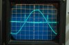
I found that the cooling & heating time constant of the lamp glass is far to slow, in the sketch attached the Lamp will ramp or dim up & down & the glass temperature does not alter much at all.

I just quickly tested an LDR circuit & this can follow the light intensity up & down without an issue with a lot less delay in the sketch than shown. I think this may be the best bet to control the light intensity rather than the temperature of the lamp glass which is way to slow to respond.

I know it's rough but it works?

Cheers, see sketch below:


/*Modified Sketch:

Willeng 18/7/2014

Interupt Pin 2 Mega
*/
int TRIGGER_PULSE = 3; // Output to Opto Triac pin
int POWER = 128; // Power level (1-128) 1 = ON, 128 = OFF (1 = 240V AC & 128 = 12V AC with my circuit)
void setup()
{
pinMode(TRIGGER_PULSE, OUTPUT); // Set the Trigger Pulse as output:
attachInterrupt(0, zero_crosss_int, FALLING);
}
void zero_crosss_int() // function to be fired at the zero crossing:
{
// Firing angle calculation :: 50Hz-> 10ms (1/2 Cycle)
// (10000us - 10us) / 128 = 78 (Approx) (I am using 71 as this tunes my circuit better & can achieve full power down to 12V AC)
int power = (71*POWER);
delayMicroseconds(power); // Off cycle
digitalWrite(TRIGGER_PULSE, HIGH); // triac firing
delayMicroseconds(10); // triac On propogation delay
digitalWrite(TRIGGER_PULSE, LOW); // triac Off
}
void loop()
{
POWER = 115;
delay(10);
POWER = 105;
delay(75);
POWER = 95;
delay(75);
POWER = 85;
delay(75);
POWER = 75;
delay(75);
POWER = 65;
delay(75);
POWER = 55;
delay(75);
POWER = 45;
delay(75);
POWER = 35;
delay(75);
POWER = 25;
delay(75);
POWER = 15;
delay(75);
POWER = 1;
delay(75);
POWER = 15;
delay(75);
POWER = 25;
delay(75);
POWER = 35;
delay(75);
POWER = 45;
delay(75);
POWER = 55;
delay(75);
POWER = 65;
delay(75);
POWER = 75;
delay(75);
POWER = 85;
delay(75);
POWER = 95;
delay(75);
POWER = 105;
delay(75);
POWER = 115;
delay(75);
POWER = 128;
delay(10);


}
 
Last edited:
Try using the rising edge and compute the time using 10,000 us, BUT always subtract a fixed offset. If your lucky, you'll be able to manipulate the fixed offset so zero co-insides with the zero cross.

e.g. the rising edge is the pre-zero cross. Delay until zero is reached. Compute how much of 10,000 us to fire.

Firing at zero, should be able to give you zero if the delay is right.

===

Another step is to fire repetitively with a short pulse at some spacing. There will be no effect with a lamp, but might be with a motor. The triac datasheet should help determine those numbers.
 
Thanks for the reply, I will check it out now & post the results..

I had some strange behaviour from the circuit & went the other way to correct it but i'll try again now knowing what I am looking for from your post.

Cheers
 
I'll let you go at it for awhile, but another thought is you can now measure the TRMS values at different turn-on times, hence you can get V and V^2 by measuring V.

==

In the long term, 0 and 100% are special cases. 0 = don't turn on at all and 100% is always turn on with possible additional "out of bounds" checks.

==

I think as you increase the "fudge factor" at 0%, you will see a decrease in intensity and then 100% with a small dead spot between them. You want to choose the middle of the dead spot.

==

Without a perfectly aligned zero cross, you might be best to empirically determine the delay. You can get a better handle of the time, by measuring it on your scope.

==

You did good making a quick program to play.

==

As for the light bulb, I think it's still a better choice to evaluate PID because it has lags. If the control was proportional, then you don't need much derivative or integral times. Not all temperatures work well for the test because at low temps, the bulb never gets to cool off, i.e. Don't expect to control at 35 C. Higher temps will be better. The same constants don;t work at all temperatures.

==

A reminder is that a "step-change" in a setpoint must be used to evaluate the suitability of the PID constants.

==

EDIT: fudge factor, quick program. light bulb, PID constants.
 
Last edited:
Thanks Kiss,

Yes I will have a better look at it all today, last night I was able to achieve as low as 2.8V AC but still I have to learn more about things obviously, it's all very interesting.

There's some good information in your last post for me to try out, I see now what your saying about the lamp with the PID when I get to it, I was thinking of it differently.

I will work on your advice with things today & see if I can get some results with the basics first & post what I have or haven't got when done.

One step at a time.

One never realises how much you don't know about things until you try it first hand yourself, I have a lot to learn!

Cheers
 
I don't want to step ahead too far, but if you get bored take a look at this datasheet for the MAX78615
:
http://www.maximintegrated.com/en/p...-energy-measurement/MAX78615+LMU.html/tb_tab3

It's an energy meter and lots of manufacturer's make them. s. It would be one way of measuring the RMS voltage and doing a correction. The I2C but operates at 400 KHz.

Dunno if it's a good idea or a bad one or even a good choice. If you could poll the value periodically and then adjust the output. e.g. poll it in a regime where your not likely to operate.

So, this would be, "a way" of doing line voltage compensation.

==

It seems to have an over current output, but not sure how to incorporate it.

==

FWIW: There is a company http://www.proto-advantage.com/store/ that will buy a Digikey part and mount it on a DIP PCB and ship it to you.
 
Here https://www.google.com/url?sa=t&rct...RbVmKQhddO-bZnw&bvm=bv.71198958,d.aWw&cad=rja is a process controller, that I'm intimately familiar with.

When you ordered it, you got the configured model and then there was a configuration guide where you could change things. This is a "very different" than a temperature controller.

https://www.google.com/url?sa=t&rct...ua1Cfq8HQHl6z0Q&bvm=bv.71198958,d.aWw&cad=rja

Just note the gazillion number of options

Furthermore, it came with operating instructions too. The 818P was a ramp/soak controller.
 
It would seem the best that I can achieve is around 3V AC being the lowest where things are stable.

If you try to adjust things nearer to 0V a couple of things happen.

Firstly as the voltage ramps down to 0V it will settle nicely but then just before the Voltage ramps up again it will give a quick spike (Flash of the Lamp) & then ramp up smoothly. It will do this continually.

If you try to get even closer to 0V, the voltage will ramp down & settle but very quickly the signal on the scope looks more like a rectified DC signal, not good I would suggest?

There is about 5uS adjustment between stable or not but 3V is it where it is stable.

With this in mind although not perfect, for the purpose of controlling the lamp at this stage & also the Universal Motors this is not a bad thing.
For the Universal Motors on the test bench the minimum power required would be about 25%, even now with the two Triac circuits I have the lowest they would go with the Potentiometers turned right down would be about 25% power which is ok.

Starting them from zero power will never happen or is never needed.

I noticed on the scope that the zero cross circuit output to the Arduino was distorted so I combined a Schmitt trigger into the circuit, it now has a nice signal which I thought would help but no luck or improvement there at all.

I am now looking at other things that were mentioned before going any further.

The Attachment will give you some indication of how the day proceeded, it's all good & am enjoying it.

Cheers
 

Attachments

  • 1.gif
    1.gif
    242.4 KB · Views: 200
3 VAC is pretty small. You could not control at 3 VAC anyway. Back to 0 being a special case where you don't turn it on at all. i.e. OFF.
 
Sorry for the delay,
One of our neighbours, a farmer had a very bad accident a couple of days ago & is in hospital, we have been helping out looking after the children for them which has been a handful.
I'll get back onto things now, if I can remember where I was up to?
Cheers
 
Status
Not open for further replies.

Latest threads

New Articles From Microcontroller Tips

Back
Top