0. The transistor used here is as a switch that on and off repeatly. What is the ideal freq. of this on & off?
1. The transistor used here is as a switch that on and off repeatly, so it is only produce pulse DC ( no negative pulse). Is it as good as the pulse that has negative pulse ( for example: pure sinus wave)? How about the efficiency between them?
2. The trafo used in this thread probably rare to find and have thin wire, that make me care the thin wire will broken when i apply about 500mA current. So, i will use regular household adaptor that is easily founded, 3V at the primary and 240V at the secondary winding, rated 500mA. Is it OK? Or maybe have to be rated 1A?
3. If above regular trafo is used, which freq. is suitable that generate by the 555 (at pin 3)? Is it 50/60Hz?
4. Is there more suitable trafo beside above regular trafo?
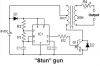
5. What's the function of D1 (4148)? Is it safe if it's not used?
6. What's the function of D2 (4005)? Is it safe if it's not used?
7. If i use 6V as the input to the 3V (written on the trafo) input for above trafo, i will get 480V (240V x2) at the output. Is this right?
8. What are the rules so that the output can show arch/spark jump (i want just only 1mm gap). What is the minimal volt and minimal ampere at the secondary trafo?
9. I wonder the pulse that generate by the 555, has it negative pulse (eg. 5V, 0V and -5volt) or only positive pulse (eg. 5V and 0volt)
10. Is it needed to put capacitor (for example: 10uF/400V) at the secondary of trafo? or maybe up to 20 capacitors @10uF/400V paralled? just to make more painful.
11. If capacitors above is attached, what rectifier is best? Halfwave or full wave rectifier?
12. Can voltage multiplier ( a diode and a capacitor) used at the output? Is it possible?
13. If the output is shorted to make spark, will this action make the component like transistor, or trafo , or IC555 broken?
14. To make more painful, i've maybe crazy idea. Why just make 2 or more unit of this thread's project. But all are powered by same power supply. If for example, we make 2 unit, we have 2 independent output (from trafos), right? I think It's clever to put these 2 output in series, so if for example, one output is 480volt, by putting in series, we got 960volt (480V x2)
15. I also interested in the swatter ( electro racket to stun mosquito/flies)
-It use just only a transistor and a resistor for providing oscilator, is full sinus is produced by this oscilator?
16. I also interested in the swatter ( electro racket to stun mosquito/flies)
-At the secondary side (where the big capacitor is), a diode (halfwave rectifier) is used, i think this is not eficient, and i plan to replace with fullwave rectifier (4 x 1N4007). Can you give comment about this?
17. How much does TIP31 cost? Is it expensive?
18. There are also TIP31A/B/C , what's the difference with TIP31?
19. Can you suggest "alternative transistor" for TIP31 that maybe cost cheaper?
20. I'm very interested in stunner / spark generator. If i only use 2 AA NIMH battery that each has 1,2 volt 2400mAh, so the total voltage is 2,4volt, can i make strong/deadly stunner? any idea? May be by increasing the capacitors at the output, or use voltage multiplier ( diode and capacitor), or by making many unit and series the output from each trafo. Can you suggest ultimate posibilty strongest stunner, by using only 2,4V ( form 2 NiMH battery)
21. If only use 1 NiMH battery that has voltage 1,2volt 2400mAh, is it posible to make medium stunner?
22. Out of topic, if we compare small adaptor trafo ( for example: 100mA,200mA, 500mA) with larger ampere adaptor trafo (for example: 1A, 5A, 10A trafo). Do they have difference in efficiency? Is larger the ampere of the trafo, the efficiency is better? maybe because of the bigger the diameter of the copper wire of the trafo, the resistance is also decrease, so the resistance loss is smaller. I've also same Nokia handphone adaptors, they have the same size, but the weight is not the same.When in use, the one is hotter than the other, can you explain this?
")
")