Electro Tech is an online community (with over 170,000 members) who enjoy talking about and building electronic circuits, projects and gadgets. To participate you need to register. Registration is free. Click here to register now.
Welcome to our site! Electro Tech is an online community (with over 170,000 members) who enjoy talking about and building electronic circuits, projects and gadgets. To participate you need to register. Registration is free. Click here to register now.
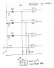
Would the 3.3V zener be big enough? I guess it would be as I would set the circuit up for around 4V using a 3.3V zener. How large can we go with the zeners/input voltage?
What's the reasoning behind the 22K resistor? Pardon the latter question, I'm just not used to interfacing digital logic with something thst is so not digital.
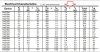
mbarazeen implied that the supply voltage to the ICs would be 3.3 Volt. So I also made that assumption. Thus a 3V3 Zener should be adequate. However, you need to check the Zener spec as low voltage Zeners don't have a very sharp "knee".
The limit to the input voltage is set by the current source voltage limit. Check its spec.
The 22 k resistor is necessary to limit the current into the IC input protection diodes.
There is also a trade off between it and the 100 k. The 100 k is necessary as a "pull down resistor since:-
1. the Zeners will have some leakage current
2. the CMOS logic has a very high input resistance (around 10^12 Ohm) so their inputs must not be allowed to "float".
As I said above, the low voltage Zeners don't have a sharp knee, so the current through them at voltages less than the specified Zener voltage must be checked.
The higher voltage Zeners ie. > 6 Volt have a sharp knee and small leakage current below the knee. So you could probably use a higher than 100 k resistor for those cases.
I did not check the Zener specs, the 100 k is an educated guess.
you are correct and it eliminates the need of two ICs, i suggest the OP to do some practical experiment to finalise the values of ressitors. its easy to solder a prototype and get it checked on the bench.
you are correct and it eliminates the need of two ICs, i suggest the OP to do some practical experiment to finalise the values of ressitors. its easy to solder a prototype and get it checked on the bench.
This site uses cookies to help personalise content, tailor your experience and to keep you logged in if you register.
By continuing to use this site, you are consenting to our use of cookies.