I would just use a serial connection from a UART. You only need to send one character, of 8 bits, so a PIC like a 16F627 would do that fine.
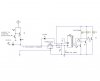
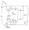
If you want to send a signal on the power wire, you will need a low baud rate, a transistor to drive the line, and a diode and capacitor at the receiving end to keep the power on while the character is being sent.
The UART transmit lines are high when no data is being sent, so that would go through the diode and charge the capacitor. When the character is being sent, there is a "Start" bit, which is low, 8 data bits, and a "Stop" bit which is high. After that the lines goes high again. (As there is no voltage transition at the end of the "Stop" bit if no more data is sent, the end of the "Stop" bit isn't a physical event)
Anyhow, if you just encoded each light as one bit of the 8 that you sent, you can send 8 independent bits with one character. For lights you would only have to send the data maybe 10 times a second at most, so the line would spend most of its time high.
As long as the capacitor could keep the power on the PIC while the line drops low during the transmission, it wouldn't reset. The lights could be powered from the line directly, as they would only turn off for an instant, so there would be no problem seeing which ones are on.