Continue to Site

Welcome to our site!

Electro Tech is an online community (with over 170,000 members) who enjoy talking about and building electronic circuits, projects and gadgets. To participate you need to register. Registration is free. Click here to register now.

  • Welcome to our site! Electro Tech is an online community (with over 170,000 members) who enjoy talking about and building electronic circuits, projects and gadgets. To participate you need to register. Registration is free. Click here to register now.

Status Light Control

Status
Not open for further replies.
Not quite working yet...

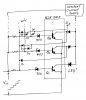
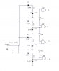
The circuit in my head was along these lines. It's a take off of the zener based bar graph display.

status lights1.JPG

But I haven't gotten it working in the simulator yet. I know I missing something.

After it does work, it won't be finished because the brightness of the lamps (indicated by LEDs in the drawing) will vary with the input/signal voltage.
 
That is an interesting idea. The lamp brightness can be solved with a current source as I have drawn in the attachment - assuming you can turn one lamp off when the next one is turned on.

My circuit uses a nightmare of diodes to do that.

When Vin rises enough to turn Q1 on, LED 1 glows.

When Vin rises enough to turn Q2 on, Q2 shunts Q1 so it goes off.

When Q3 goes on it shunts Q1 & Q2, etc.
 

Attachments

  • ULN Option.jpg
    ULN Option.jpg
    244.2 KB · Views: 115
Though I've not read the ULN2003 datasheet recently. I thought the input was logic level. That's the only way I've ever used it.
 
Though I've not read the ULN2003 datasheet recently. I thought the input was logic level. That's the only way I've ever used it.

The data sheet states that the max input required for a 200 mA collector current is 2.4 Volt.
 
But I haven't gotten it working in the simulator yet. I know I missing something.

After it does work, it won't be finished because the brightness of the lamps (indicated by LEDs in the drawing) will vary with the input/signal voltage. A current source will fix this if you can design it so only one LED is lit at a time.

I have fixed your problem.

Q33 will now have base current via D2 once the input voltage rises to approx 4 Volt & above.

However, you still need to find a way to turn off all LEDs except the active one. I can't see an easy way to do that.
 

Attachments

  • status lights2.JPG
    status lights2.JPG
    115.8 KB · Views: 118
Last edited:
Only one is on at a time. They will be selected by a relay output. But now I'm adding a circuit to the mix. The price advantage is slipping away.

ok, i got the idea how to signal it too, you can use another 4017 at the other end and it will be wired through the relay out puts. shortly i will post you the schematic.

finally you will need the following components.

4017 - 2nos
NOR gate IC - 4001 - 1
transsitors - 7 or as required
zener- 1
capacitor -2
some resistence

all together it will cost not more than a dollar when you buy it in bulk.
regarding PCB all can be made as one PCB and splitted into two when wired. more the quantity you need the lesser you pay.

Edit: see the attached CCT, at the signal end another 4017 connected via rleays normally open contacts. at begining when power "on" both counters will reset & remain at the same out put. when ever one contact is closed, then the out put of the status 4017 will follow out put of signaling 4017. You have to wire both of them in similar incase you make a reset feed back, other wise you can let it to reset internally. hope it would be a simple solution for your task & cost effective too.
 

Attachments

  • status light cct modified.JPG
    status light cct modified.JPG
    59.6 KB · Views: 121
Last edited:
Here is an improvement on the ULN option I posted a day or 2 ago.
 

Attachments

  • ULN Option 2.jpg
    ULN Option 2.jpg
    225.9 KB · Views: 124
Last edited:
I don't see why you would need to use a ULN2003 in that circuit. I think that's the design arrangement I was after. The current source could be tied directly to Vin if the leds each had their own resistor. The resistors would need to be sized for the voltage range over which they were expected to operate. But then again, there is no "range" there is just the step pattern you describe. I'm going to try a spice model using good ol' trusty 2N2222s later.
 
That's it! I was correct in that a current source would not be needed due to the stepped voltage inputs with the caviat that the current limiting resistor for each LED needs to be sized for the respective step voltage. In addition, the zener voltage can't/shouldn't be the trigger voltage. The trigger voltage needs to be above the breakdown voltage and away from the knee and breakdown curve. If the zeners selected are 3.3, 4.7, 5.6, 6.8, 7.5, etc. the trigger voltages should be something like 4.0, 5.1, 6.2, 7.1, 8.0.

I spent most of my time trying to use NPNs to get the circuit to work, but your solution solved all the problems I ran into.

I'll be presenting the transistor ladder circuit and a variation of the LM3914 circuit to see which one they like best.
 
Last edited:
Yes, you don't need the current source if you have individual resistors for each LED.

But that is more components. A CS is one component.

However, I really think the circuit I posted at post #39 is the simplest.

I have not done the calcualtions, but I think it will need a resistor beteen pins 3 & 6 in order to shift the voltage ladder voltages down a little.
 
I don't see why you would need to use a ULN2003 in that circuit. I think that's the design arrangement I was after. The current source could be tied directly to Vin if the leds each had their own resistor. The resistors would need to be sized for the voltage range over which they were expected to operate. But then again, there is no "range" there is just the step pattern you describe. I'm going to try a spice model using good ol' trusty 2N2222s later.
There are 2 reasons why I suggested the ULN2003.

1. you have 8 Darlingtons in one IC.

2. if you look at the ULN data sheet, it has resistors between the bases and emitters. So if you use BJTs, you will need a resistor between each base & emitter on every transistor.
 
Post #39 will use a ton of diodes as you mention. In the updated 2003 version, I'm not following how you would wire it. There seems to be connections to points inside the IC that you don't have access to.

Either way, I need to figure out how to build a constant current source. My last was a long time ago.
 
Last edited:
Post #39 will use a ton of diodes as you mention. There are no diodes in this post. It is the second LM3914 circuit that I posted. In the updated 2003 version, I'm not following how you would wire it. There seems to be connections to points inside the IC that you don't have access to.

Either way, I need to figure out how to build a constant current source. My last was a long time ago.
If you use the LM3914 option, it has all that you need inside including the constant current sources.

The LM334Z is an adjustable CC source,
 
Post #39 will use a ton of diodes as you mention. In the updated 2003 version, I'm not following how you would wire it. There seems to be connections to points inside the IC that you don't have access to. NOT TRUE!

Either way, I need to figure out how to build a constant current source. My last was a long time ago.
I saved time by drawing the Darlingtons as BJTs.

The base of the BJT on the drawing represents the input pin of the ULN.
 
How was I supposed to know that? I thought you had just dropped some of the internal resistors. So the drawing you made uses 4 of the 7 channels of the ULN2003?
 
how are you going to push the power to the lamps keeping the voltage 12 for it when you use ladder config?
also the cost for PCBs will be based on number of holes you request from manufacturer. compare it with my last circuit in post #46

also did you consider any voltage drop over the conductor at full current required?
 
Last edited:
How was I supposed to know that? I thought you had just dropped some of the internal resistors. So the drawing you made uses 4 of the 7 channels of the ULN2003?

I was illustrating the principle.

Had someone done that drawing for me, I would have understood that.

The details are for you to decide.

Yes, the drawing shows 4 of the 7 Darlingtrons.

Note that the ULN2805 has 8 Darlingtons and the max input voltage necessary for a collector current of 350 mA is 2.4 Volt.

Also note that in the drawing, the resistor connected the the base of Q2, 4, etc. is the internal resistor. An external resistor is not necessary in those cases.
 
how are you going to push the power to the lamps keeping the voltage 12 for it when you use ladder config?
also the cost for PCBs will be based on number of holes you request from manufacturer. compare it with my last circuit in post #46

also did you consider any voltage drop over the conductor at full current required?

Thank you for the idea illustrated in post #46.

I'm sure the OP will appreciate the effort you expended in preparing and posting it.

However, if you read through the threads, you'll see that I and others have suggested similar circuits.

The OP told us that he wants the sending end to be as simple as possible.
 
Last edited:
Thank you for the idea illustrated in post #46.

I'm sure the OP will appreciate the effort you expended in preparing and posting it.

However, if you read through the threads, you'll see that I and others have suggested similar circuits.

The OP told us that he wants the sending end to be as simple as possible.

that is fine, also it can be digitally implemented at the receiving end as shown on the attachment.
 

Attachments

  • status light cct.JPG
    status light cct.JPG
    25.6 KB · Views: 120
That is an excellent idea. Thank you. Some suggestions:-

I would not include the 3.3 Volt Zener diodes since the input protection diodes in the gates will do the overvoltage protection.

I would increase the 1 k resistors to 10 k.
 
Status
Not open for further replies.

Latest threads

New Articles From Microcontroller Tips

Back
Top