Continue to Site

Welcome to our site!

Electro Tech is an online community (with over 170,000 members) who enjoy talking about and building electronic circuits, projects and gadgets. To participate you need to register. Registration is free. Click here to register now.

  • Welcome to our site! Electro Tech is an online community (with over 170,000 members) who enjoy talking about and building electronic circuits, projects and gadgets. To participate you need to register. Registration is free. Click here to register now.

Status Light Control

Status
Not open for further replies.
Here's a design challenge for you all (and me).

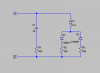
I have a series of status lights (four currently, but might be three to six) that I would like to illuminate, one at a time, using two wires, and as few components as possible. There is no order to the lights so a counter would be out.

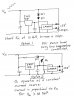
The driver behind the attempt is to reduce the conductors required in the cables and connector to reduce cost. But too many components in the solution may increase the complexity while not reducing the cost.

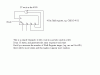
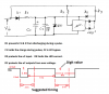
My first thought was select the light based on the voltage supplied. I can get two lights if I use a positive and a negative voltage, but that diesn't get me in the 3-6 count required. I also was pondering a zener ladder, increasing the voltage to trigger the next light, but all the previous lower voltage lights would also be on. No go there.

I look forward to seeing what you all come up with.
 
Last edited:
I wanted to do the same thing once, and used band filters, and a certain freq as trigger, there is a post somewhere about it.......
 
What about using a pseudo random counter - see attachment.

Do you want to be able to control the times that the lights change?

Or do you want it to be free running?

You would need some gates to be able to turn on each light individually.

The pseudo random counter can be made longer or shorter.

The 4 stage shift register will give you 15 states.

So, for example, if you had 5 lights, then the gating could be designed such that light 1 is on at counts 1, 7 & 11.

More states will make it appear more random.

If you want to be able to control it from the supply end of the 2 wire connection, then you could apply some type of modulation on the DC.
 

Attachments

  • Pseudo  Random counter.gif
    Pseudo Random counter.gif
    4.8 KB · Views: 150
What about using a pseudo random counter - see attachment.

Do you want to be able to control the times that the lights change?

Or do you want it to be free running?

You would need some gates to be able to turn on each light individually.

The pseudo random counter can be made longer or shorter.

The 4 stage shift register will give you 15 states.

So, for example, if you had 5 lights, then the gating could be designed such that light 1 is on at counts 1, 7 & 11.

More states will make it appear more random.

If you want to be able to control it from the supply end of the 2 wire connection, then you could apply some type of modulation on the DC.

These are status lights. The main controller will dictate which light is on. They don't get to choose at random.
 
In that case, then you would have to modulate the DC with coded pulses.

eg. a long pulse to reset the counter or shift register and short pulses to step it.
 
I could make that work as a digital solution but the part count for the receiver and transmitter may be too high. I wonder if anyone has an analog solution.
 
Last edited:
Do you have a power source where the lamps are, or are you trying to power the lamps on the same wire pair as the you are doing the selection?
 
I could make that work as a digital solution but the part count for the receiver and transmitter may be too high. I wonder if anyone has an analog solution.

You would need 2 ICs eg. a Shift Register & a Schmitt Trigger or a single IC ie. a microcontroller.

For an analogue solution, you could use the LM3914.
 
I thought of that, but the IC is not tolerant of changing the supply voltage with the signal voltage. I only have two wires, unless I find that it just can't be done.
 
Without too much thought, here is how you can do three. R1-3 are 12V grain-o-wheat lamps.

If you feed A-B with +12Vdc, you light up R2, but not R1 or R3
-12Vdc, you light up R3, but not R1 or R2
12Vac at >1kHz, you light up R1, but not R2 or R3
12V square wave at ~50Hz, R2 AND R3, but not R1

and you can get the other combinations (8 total) by independently controlling the AC source and the DC/squarewave source.
 

Attachments

  • 3lamps.png
    3lamps.png
    4.3 KB · Views: 141
Of course I have. What orientation did you have in mind?

Yes, I know you do, I was just stirring.

See attached. You may have to vary the step size as the voltage increases to account for the increasing voltage through the Zener(s).

I have drawn the basic idea, some other components will be necessary as per the LM3914 spec.
 

Attachments

  • Options.jpg
    Options.jpg
    313.1 KB · Views: 132
The advantage of the digital solutions is that they are much less critical, ie. you only have to detect the difference between a pulse & no pulse.
 
Here is a suggestion.

A microcontroller (uC) would be a simple solution see attached.
 

Attachments

  • uC Option.png
    uC Option.png
    176.7 KB · Views: 126
How about a DTMF encoder on the send side and a DTMF decoder on the receive end? That could easily give you 12 channels over two wires.

Ron
 
you can simply use a 4017 counter, make it reset when power on, use a regulator to supply. say you provide 6V & use 5V regulated out to 4017.

connect the clock input via a 7V zener from the source before the regulator also conenct a low resistance at the clock input. so now your voltage would be 6V & no voltage at the clock input.

now you can increment the count by increasing the voltage to 12 ( pulse of 6-12V), number of pulse would set the state of the counter. for the next state, the controller at the other end would decide howmany pulse to send.

sorry i couldnt sketch a circuit
 
Status
Not open for further replies.

Latest threads

New Articles From Microcontroller Tips

Back
Top