gramo said:
Nice work Kiko, I'm glad to see a whole project pan out so well, if you decide to throw in a temp sensor, maybe this will help
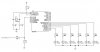
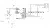
The datasheet shows many ways to use the LM35DZ, but I'm using the example on page 7 in the datasheet, with the
-55 to +150 degree C application. It requires 3 additional components, 2 * 1N914 (Or 1N4148), and 1 * 18K resistor.
**broken link removed**
Code:
Device 16F877A
Declare XTAL 4

DECLARE ADIN_RES 10               ' 10-bit result required
DECLARE ADIN_TAD 8_FOSC      ' Set the ADC's clock source
DECLARE ADIN_STIME 50            ' Allow 50us sample time

Declare LCD_TYPE 0                   ' Type of LCD Used is Alpha
Declare LCD_DTPIN PORTB.4     ' The control bits B4,B5,B6,B7
Declare LCD_RSPIN PORTB.2     ' RS pin on B2
Declare LCD_ENPIN PORTB.3     ' E pin on B3
Declare LCD_INTERFACE 4         ' Interface method is 4 bit

Dim ADC_Result As Float
Dim ADC_Total As Float
Dim Temp_Float as Float
Dim ADC_Channel as Byte
Dim ADC_Loops as Word
Dim Temp as Word


Dim Last_Result1 As Float
Dim Last_Result2 As Float

ADCON1 = %10000000                     ' Set all to analogue inputs (PORTA)
TRISA = $FF                                    ' Declare porta as all inputs

Delayms 150
Cls

Print $FE,$40,$07,$05,$07,$00,$00,$00,$00,$00 ' Custom character for Degree

ADC_Loops = 200

Main:

ADC_Channel = 1                     ' ADC on first reference
Gosub ADC_Average                ' Perform an averaging to enhance accuracy

Temp_Float = ADC_Result        ' Store the result

ADC_Channel = 0                     ' ADC on second reference
Gosub ADC_Average                ' Perform an averaging to enhance accuracy

ADC_Result = ADC_Result * 5000 / 1023           ' Convert values into Volts (with a scale of 1000)
Temp_Float = Temp_Float * 5000 / 1023            ' to reduce decimal error
ADC_Result = ADC_Result - Temp_Float           ' And calculate difference

ADC_Result = ADC_Result / 10                        ' Scale back down remembering 10mV = 1 Deg C

If ADC_Result <> Last_Result1 Then               ' Check if the data has changed
Print At 1,1, Dec1 ADC_Result, 0, "C "             ' and only update display if it has
Last_Result1 = ADC_Result                              ' Store new data
Endif

Goto Main                                                       ' Loop for ever


ADC_Average:                                                  ' Perform an averaging on ADC conversions
                                                                       '  to reduce errors
ADC_Total = 0                                                  ' Clear summing register
For Temp = 1 To ADC_Loops                            ' Loop for a pre-determined number of times
ADC_Result = ADIN ADC_Channel                    ' Grab a new ADC value
ADC_Total = ADC_Total + ADC_Result              ' Sum it to the total register
Delayus 1                                                        ' Allow internal capacitors to discharge
Next Temp

ADC_Result = ADC_Total / ADC_Loops              ' Determin the average of all the equations

Return
The comments went all over the place, but you should be able to ge tthe jist of it
All right Sir thanks a lot for your help, That's the help I want to see in the forum. I really apreciate it.
But I have in hands a Dallas 18B20 temp sensor and I think I'm going to use it, with the code below (just for example).
DIM Temp AS WORD 'Holds the temperature value
DIM C AS BYTE 'Holds the counts remaining value
DIM CPerD AS BYTE 'Holds the Counts per degree C value
Deg CON 223 'Shows the symbol Deg °
OWRITE DQ, 1, [$CC, $44] ' Send Calculate Temperature command
REPEAT
DELAYMS 25 'Wait until conversion is complete
OREAD DQ, 4, [C] 'Keep reading low pulses until
UNTIL C<>0 'the DS1820 is finished.
OWRITE DQ, 1, [$CC, $BE] 'Send Read ScratchPad command
OREAD DQ, 2,[Temp.LOWBYTE, Temp.HIGHBYTE, C, C, C, C, C, CPerD]
'Calculate the temperature in degrees Centigrade
Temp=(((Temp>>1)*100)-25)+(((CPerD-C)*100)/CPerD)
PRINT AT 2, 11, "OAT=", DEC Temp/1000, ".", DEC1 Temp, deg, "C "
Thank you again and I will post as soon as I can this project using a Graphic LCD.