I have always been paying VERY big attention to my 180* shifts with toroid/connections/inverter count.
I think you didnt understand what I meant.. I am not flipping 180*... I was on one schmitt, then ran the secondary ground through the toroid in the opposite direction i had it. This flips 180. Then I added another schmitt, this adds another 180*. Now Im back "360*" to where I started. It runs very crappy with two schmitts(on same Phase cycle). I think it changes when adding one more schmitt due to the propagation delay the second adds.
No, I read this thoroughly and understood it. You have to understand that you are not the only one reading this thread. Sometimes I need to explain certain concepts for the benefit of other current and future readers. The point of my post was mainly to look at the delays caused by the different parts of your circuits (i.e. the propagation delay of the Schmitt trigger inverters and of the RC filters). I think you need to go back and reread
my posts as you clearly are not understanding the intent behind them.
I really do understand you know a ton more then I do about this stuff but the one thing that has held us back this entire thread is you assuming I don't know something therefore I have to re-explain it. I understand my grammar might suck but you would have seen the part about the secondary ground if you where not assuming everything.
I am assuming very little. I take what you write, I read it (often two or three times), and then I respond, sometimes adding background information for other readers, and to verify what you have already done. What has been holding us back this entire thread is you refusing to provide
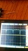
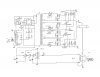
all of the necessary information. You STILL haven't posted any detailed photos of your setup, and all of the schematics you have posted are either incomplete or have been changed in your actual setup. All that on top of not using the right tools for the job makes it very difficult to help you.
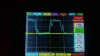
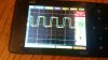
It will not work with no caps and through one schmitt, it will on antenna.... you saw my Previous phase shift on CT I'll test with my #2 setup and see If its less then the 1us the last shift was. I have tied a lot of combinations here and out of 115 this is the first one(#2)...
That's another thing, without detailed images from a high bandwidth scope, it's difficult to track down where your problem is. I know I've been saying this over and over again from the start, but that's only because it is more important than you seem to realize, and you just keep blowing it off. "Oh, this scope has worked fine for me in the past." "Oh, I plan to get a better scope sometime." None of this is helpful NOW, and expecting detailed help without providing decent waveforms, schematics, photographs, etc. is unreasonable.
What I was asking in that post is if it working with one schmitt is okay?
I answered this in my last post.
Also my resistance has been changed to 56ohms. So 1/(2*pi*R*C) = 12918.42hz. does this make my RC constant better? Maybe this is moving me 180*out and if I invert that I'm back in to phase.?
Changing the resistance to 56 ohms definitely helps the delay (your RC time constant is now 12ns) but now you have a filter that is practically useless (and FYI the fc with an R of 56 ohms and a C of 220pF is 12.918MHz, not 12.918kHz). Your filter wouldn't begin having an effect until the ~75th harmonic, which is absolutely useless. Theoretically you'd be better off taking it out altogether, which is what I mentioned earlier. We would need to determine the reason
why adding a filter
seems to be helping, and solve the problem further up the chain closer to its source. I think it's sheer chance that it is actually helping. The actual problem is most likely much deeper and you're just sticking a band-aid on it.