Continue to Site

Welcome to our site!

Electro Tech is an online community (with over 170,000 members) who enjoy talking about and building electronic circuits, projects and gadgets. To participate you need to register. Registration is free. Click here to register now.

  • Welcome to our site! Electro Tech is an online community (with over 170,000 members) who enjoy talking about and building electronic circuits, projects and gadgets. To participate you need to register. Registration is free. Click here to register now.

Solid State Tesla Coil Burning Mosfets

Status
Not open for further replies.
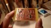
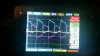
I think I found my issue. If you look at my Gate driver output, it is triangled slightly on the top and a bit better square on the bottom. This is making two fets turn on longer then the other two. Derstrom got me worried about R7 and C2 causing unnecessary charge delay. So today I was able to remove R7 and reduce C2 down to 68pf. Hopefully that helps that situation. This Gate output is the same between those two orientations. So this is where I'm stuck, I dont know how to square that more evenly, I figured the inverters would take care of that. The only thing I can think of playing with is the CT toroid since this is the signal I am getting from. I dont think the turn could will change how the inverse of the wave will look. So Im stumped here. I also tried adding another two inverters but signals the same.

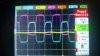
The picture below is a image of a Low Side Fets GDT Gate signal. The purple is the inverse, you can see the tops of the purple are pointed compared to the blue.

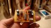
I know this wil be the third time correcting this, My meter was about dead. I did only pop 2 fets on the last run. Same switch, opposite output rail. these two where ones with the pointed waveform(purple)
 

Attachments

  • IMG_008.BMP
    38 KB · Views: 133
Hey so I'd figure I'd at least continue.. I'm getting closer for sure.

The only thing to me which may be wrong, is the trangled inverse of my gate waveform was in my opinion due to added stray capacitance from using a Breadboard(I read every connection can add 2-25pf, WOW). So I. Made a driver board as u can see below.

After changing this to printed board I then viewed the Waveforms, way more square, especially my CT inverter output(pic 21501). That was a gigantic difference. Ill probably play with those cap values a bit more since every waveform is way different. (you guys called the hell out of that)

I then probed my Mosfet gate waveform. I posted pictures below, the higher voltage looking one(1402.jpeg) is with a 1 if cap(DC blocker), the shorter version(4727) is with an unknown value cap, I'll check tomorrow but its one of the brown polyester film types 250v(Not in picture below). So to me that one looked the best to me. These waveforms looked a ton better then on the bread board.

The one issue in the Waveforms that I can see is the duty cycle not even. My scope is reading 55% duty. This goes all the way back to CT/ or antenna. Is this normal? If this is not okay, how do you change the duty cycle if its generated from my feedback signal(CT turns maybe)? This will cause one side of my bridge (2 fets) to be on for a shorter period then other two. Not sure if this is bad, or how to change that.


I am also not sure on the best Waveform for your gdt. I did find a cap value that looks fairly square but with a slight overshoot on the rising edge. So tomorrow I will also post some scope pics of a few blocking cap variations.


Thanks again guys,
Especially DerStorm8
 

Attachments

  • received_10208571416195234.jpeg
    received_10208571416195234.jpeg
    166.8 KB · Views: 145
  • received_10208571416155233.jpeg
    received_10208571416155233.jpeg
    170.9 KB · Views: 121
  • received_10208580596024724.jpeg
    received_10208580596024724.jpeg
    179.5 KB · Views: 117
  • orca-image-1496865558754.jpg_1496865561402.jpeg
    orca-image-1496865558754.jpg_1496865561402.jpeg
    381.9 KB · Views: 124
  • 21501.jpeg
    21501.jpeg
    851 KB · Views: 149
Last edited:
The only thing to me which may be wrong, is the trangled inverse of my gate waveform was in my opinion due to added stray capacitance from using a Breadboard(I read every connection can add 2-25pf, WOW).

Wow, who told you that? When did it finally sink in? Couldn't have been anyone here, since you kept resisting our telling you that. :)
 
Hahaha hey hey that was the first things I did. Lol yes it took me two weeks for both, and one more try after one was made. But yes thank you as well, I know you where involved in that. And yes I do understand I was straying from that but I just didn't understand how much a small capacitance can affect a high frequency waveform.

So I'm sure I'm right there tho. I did find through more research that my duty cycle being off is due to my CT blocking cap. I did try a bunch of combinations and what I has was the best. 55/45 was the best I can do. I tried adding another DC blocking cap on the ground end of the CT for sh*ts and gigs and it made my duty stray further apart. So I'm hoping 45/55 is doable for a SSTC with IGBT's.

I did find the reason why I can't add to many turns to my primary. I thought 3 was best tuned. No way. I did notice its based on how far I am away from it being a DR and dual resonating. Right now on two parallel 20v labtop supply's, with the 4.7uf cap I get 2mm of arc off my breaking point. Now I swapped to a 220nf 400v cap for my low power( this helps me diagnose better since I can see) now I did the math, on 3 turns that's very close to a DR. I'm okay with that on low power but wow! My 2mm turns into 3cm, coming close with a screw driver I get maybe 6-8cm. Now okay this made me think of turns after a wile. So I put my helical 6 turn back on, now with the 220nf cap it's almost exactly like my 4.7uf cap(2mm arc). I changed my cap to a 510nf it's back to 3cm. Now as I change my turn count, from there I get weaker as I go up or down in turns.

So this at least tells me as I go farther away from a DR it gets weaker, this is expected. But if I get to far I get no output. So I thought this maybe was input power, maybe not enough. Well wrong again, I tried on mains previously with my 4.7uf on 6 turns and it would not fire up. Even 4 turns had trouble. So I'm stumped here, do I need to loose the cap? I see lots of people with and without. I also have tried it and it works. Only crappy part is if I ever blow two fets again, it'll be 4 not 2.

I do feel I'm getting close here. Biggest improvements I can see are PCB boards and CT working.

The pics I promised today are to big I'll add them later tonight when I'm on my computer. Also that unknown cap value for GDT DC blocking is a 580nf. I think that's the one I'm ganna stick with.
 
This most likely is a question for DerStorm, If you could please answer this, Im sure your the only one who understands this. I was reading on DRSSTC's, I found Kaizers DRSSTC paper online and was interested in the DC snubber capacitor section. So I took another look at my bridge output(loaded)

I think the scribble is the tesla ring, or noise. when making my own pulsed input unloaded these looked just like the gate input.
9.JPG

I can see voltage spikes, these rise to 64V on my low power supply. This makes me think on high voltage I'm shooting voltage transients into these Fets that exceed the rating. This make my completely understand your comment on how they can pop without heat. I thought with Zeners and shoot through diodes I was covered. This was written in a way to make me understand, as well, what a couple other people where talking about in previously read papers. From what I understand from his write-up, a Snubber Cap would seem to benefit me. I cant find a specific paper online about snubbers on tesla coils. As well he doesnt have a schematic showing what he means. So Im not sure where or how to do this on a tesla specifically. I see separate circuits with a resistor and cap in series calling it a snubber, Im sure this would differ on a TC an am not sure how to apply it.

I also attached his image of how snubbers help.
snubberwaveform.jpg


These are updated videos on the TC running with both PCB boards. It seems to run fantastic!!!! In these videos I did alter capacitance and primary for best arcs and highest currnt on my low voltage power supply. One video is in CW mode, the other is modulated. CW can run for 10mins and Fets are cool, caps and power wires get very HOT!!! LOL (Need to up wire gauge)

Primary - Helical 3 turns, 14 AWG, 4", 0.375" spacing
CAP - 3 parallel 10/10 600v caps, 310nf measured ( I think film, there in video, I'm not sure, there old)
POWER - 2 20v Laptop supplies, Pulls 4.2amp @ 20v


CW MODE


Modulated
 
Last edited:
With a little more reading on snubbers, This may be a bad idea, I read they can introduce more problems then they fix.

I did figure with the change to pcb the bridge inductance would be at the minimum. Do the wires leading to my primary from the bridge count? I see this grayed out in a lot of examples but it seems to me a long wire could make this increase voltage transients.

So I did see a couple designs with people using MOV's or TVS diodes in parallel with the freewheeling diodes. This to me sounds reasonable, Although the value to use is something I wouldn't know. My best guess on value for TVs diodes would be around 200v. I get a bit of buffer room both ways, 175v rail and fets are max 250v. Then there are the MOV's, I would guess the same voltage clamp rating(200-240) but they also have a capacitance value. This makes me think using MOV's could implicate the same issues involved with a snubber cap.

So with the wide variety of voltage suppression techniques people use I'm not sure whats the best.

orca-image-1497329355855.jpg_1497329356706.jpeg
 
Last edited:
Alright, So, I fished through my parts today, I had 4 20D151k MOV's. Cool! These are 70v clamp, not the ideal ones, although I can test these on my low power 20v supply since I was seeing spikes around 120-150v. As well, to ensure I minimize all of my inductance in my circuit I beefed up my Supply wires feeding my primary by 3 gauges and shorten them by half. Then soldered my capacitor in line instead of pinning to a PCB board for that capacitor. I also increased my Supply power wires.


orca-image-1497326129958.jpg_1497326130956.jpeg

orca-image-1497326191018.jpg_1497326191735.jpeg

You can see in these two scope views they are camping right around 70v. Cool no more spikes, however this is drastically killing my performance. My arcs off of my Breaking Point went from 2 to 3 cm long and about 2cm wide to then 1.5 cm long and just a straight single arc.

orca-image-1497326486584.jpg_1497326487420.jpeg

But then I see this if I come close with a piece of metal. A little side note here, all I had around me was some 600 volt capacitors so I bent a leg out and came close to my top load. Surprisingly I got a 9 cm thick white hot arc.WOW!! Wtf.(if I counted the bent rise of the arc it was 15cm).. I then actually got my screwdriver, came close to it, got half that length. For some reason that capacitor really like to Arc off one of its legs. Hmmmm. Anyway you can see in this photo, when I come close and arc off the top load, I don't quite get a voltage clamp as I do arcing to air. ou In this picture my max voltage jumped to 150 volts. This was about where I was arcing to air prior to MOV's.

So overall I see it has taken effect and has helped arcing to air, although I do have decreased performance as well. This doesn't seem quite logical. This also may be the value of the mov? All I can do is expect the same on my higher voltage Supply. If I ever want to come close with a chicken stick I'll probably pop my mosfets.

So I guess the next step would be to try TVs diodes although I may see a similar outcome.
 
Last edited:
May be totally off base here, but what your getting could be possible using a car ignition coil and an oscillator to drive it. A Tesla coil should give sparks to the atmosphere no metal or cap needed. Is this directly attached to earth ground? Not through your power supply leads, which aren't sufficient for atmospheric sparking.
 
May be totally off base here, but what your getting could be possible using a car ignition coil and an oscillator to drive it.
Yes This is true, that was my very first SGTC.

A Tesla coil should give sparks to the atmosphere no metal or cap needed. Is this directly attached to earth ground? Not through your power supply leads, which aren't sufficient for atmospheric sparking.
I'm not positive either but most lower-mid power SSTC's I have seen all say to use a breaking point. In my experience if you just have a top load, It will not arc. The breaking point I think just gives a point for the high voltage to break through the air easier.

During these last two tests with and without the Metal Oxide Varistors, I did not have my secondary earth grounded, Just bridge circuit grounded. You absolutely may be correct that a true secondary earth ground may improve atmospheric sparking. During these two tests is when I saw the reduction off my breaking point, these where grounded the same way during each test. So even though it may improve my sparks to air I'm still seeing a loss between the two.

On another note that makes me think, on the earth ground improving my sparks to atmosphere, as well My secondary being grounded on my bridge supply may be why I get those transient spikes. When I come close with metal to my topload and arc, I would think the current through the grounded secondary spikes, maybe that's all getting thrown back at may supply. I'll try that same test today with is earth grounded and see if my results alter.
 
Alright!!!! So today I tried to tackle inductance, As I re-read every SSTC or DRSSTC paper out there, I see transient spike = to much inductance somewhere. I've been going off this schematic I found online showing dark black lines on your H-Bridge that need to be kept as short and as fat as possible.
TCInduc.png


I have had very long feed wires supplying my primary since they where not highlighted on this picture as well as a few others.

Even though I did just beef those wires up, I decided to shorten them a lot today. It was about 3ft now its 6". I was trying to get as much distance between the coil and the circuit as possible. Since I saw this wasn't a problem I never looked here. After shortening them up today, WOW, I was having awesome arcs with a 310nf cap prior, Now the 4.7uf works like that did!!! Sweet!!! So I think I found a big culprit, Im at 6" of 16 gauge and my transient spikes went from 150v to 63v. So I think for my final product, as well as future testing I'll use some 8 gauge sub wire. Super flexible, Same stuff I used on my SGTC. I will also try and keep length under 8".

So Im sure this my be wrong but a 20v supply with 63v transient spikes is 3X the rail. So If I want to eventually be on mains 175V, 175 * 3 = 525v transient spikes. Now Im basing this off a plan that uses 600v IGBT's, This is under there max voltage, So my understanding is that this may work. Do I have an issue that still needs to be addressed, YES. I will absolutely not call it a day quite yet, I'd like to minimize as much of these swings as I can. The next step would be to fish through some more for any high inductive areas. I have ordered some 250v and 300v TVs diodes, as well as some 250v .5uf caps to try and reduce these swings.
 
Hey guys!! So I have done quite a bit between now since my last post. . Ill fill you guys in but without to many details.

As I left off last I was trying to tackle transient voltage spike's, and the cause, high bridge inductance. So I did completely change my project setup, I made a driver PCB as well as a rectifier board. This was all placed in a PSU box, much shorter wire as well much larger. Internal bridge output is 12 gauge high stranded count, high amperage wire to high quality gold banana connectors. I then used 8 gauge sub wire 5" to primary. I also added solid wire on top of every trace on my bridge PCB with a lot of solder to all help lower my inductance. I did notice a drastic difference doing this.

I then read up on a very important item I was missing. On the last schematic I posted, I did not have diodes on the drain, these are motorola 1n5822's in that last schematic. I read these are there to block the internal body diode, that's if your internal diodes are to slow, using external freewheeling diodes. I did not have any schottky's that would work in this location.

I then looked at the reverse recovery time on the internal body diodes in the IGBT's I got. they are twice as fast as the freewheeling diodes I was using. So I threw the IGBT's in, took the MUR460's out. Added some1.5ke220's(328v clamp) and some 330v MOV's. I also have ascertained a 20a variac. So at this point I have tested up to 70v with no issues other then secondary arcing. but NO POPPING ANYTHING!!!!!! WWWOOOO!!!!I have tackled that for now but a different issue is showing.

I have not mentioned this but in the start it seemed my gate driver would heat up depending on how I had it connected. It seems now I am hitting a thermal limit protection on the gate driver, causing this to drop at least 60% power. I remember in the beginning it was dead cold. after the 3rd or so time it fried I was re-connecting and notice it was getting super hot super fast. I ended up finding a combination that kept it cool. After re-warping my GDT with CAT-5e cable and adding a second inverter, it has been heating up fast. I wrote this off as maybe it always was and I was just not seeing it. I did add a fairly big heat sink thermal epoxied to the IC, this must not be doing the job now.

So does anyone know if I need the DC blocking cap on a certain side of my GDT compared to the DC block of my primary? Im starting to think that wasnt always happening and there is a specific way to connect. to keep from heating. I swear that was dead cold the first time, but if I flip the GDT connections it flips phase so then I need to flip the primary connections or direction. As I remember it was cool when running one inverter on CT input not two. So is there a main configuration that the GDT DC blocking cap is high or low compared to the primary DC cap??...
 
Last edited:
Really guys, I think I am so close on this it's ridiculous. I so far can't blow this thing up as much as I push it for that short period of time it doesn't cut out. I looked on the UCC27425 data sheet and could not find anything on a thermal cutoff protection. I did try to flip the GDT's connections on the gate drivers output, this should 180 my phase. So then I swapped my primary connections to 180 it back. It still makes the gate driver get hot. And I mean this thing has a 1-inch heatsink on it and gets hot hot to the touch after 20 seconds of run time. I couldn't find anything on the datasheet nor online about specific ways to connect this IC. Does anyone have any input on this, please, the seems like its my last problem here but with the amount of connections there are I would have to sit here and try over a thousand possibilities to find the right one. But I swear I do remember in the beginning this gate driver was ice cold. I even replaced it with a new one just to make sure that one wasn't fried and it's doing the same thing.
 
Could the type and or value of the DC blocking cap change this? I did notice when trying a bunch of values it would change the output voltage of my GDT significantly. I went with the highest output as well as best looking waveform. But I'm thinking, could that voltage increase be something to do with the cap value causing the gate driver to output a greater current? Maybe I change may cap back to a 1uf and see if that helps.

Edit:
Nope went back to a 1uf, no different. One thing I did realize, Most full bridge setups use 8-9 amp drivers, this says +-4amp, I took this as 3 amp on inverting and 4amp on non-inverting. Maybe its 4amps all together. If so then I am sure this is my heating problem, since I took this off a half bridge design.

Back to the drawing board, I'll most likely do the common 2 9amp driver configuration.
 
Last edited:
Hello, I have a Nissan SR20VET Xtrail T30 for which I built a modified fueling system that fooled the MAF which fooled the ECU. I monitor the fueling and other engine parameters from the ECU interface displayed on a CARputer XP SP3 7" touch screen. Did it back in 2k9.

Anyhow...on to the discussion.
I recently had to solve a bank of 4 MOSFETs popping after running for weeks as pulse drivers of 600A+, approx 250W RMS.
Turns out I was exceeding the SOA regarding the avalanche ratings even though I kept the temps down with a 3/8" x 6" x 6" Alum hsink and heavy duty 120VAC, 120mm ballbearing fan.

The solution was to make an effective snubber to handle the backemf transients. Those transients account for up to 20W of power as I measured it.
The FET MCP1407 driver runs cool to the touch.

here is the thread:
https://www.electro-tech-online.com/threads/matching-nfets.150464/page-2#post-1291398
 
Hello, I have a Nissan SR20VET Xtrail T30 for which I built a modified fueling system that fooled the MAF which fooled the ECU. I monitor the fueling and other engine parameters from the ECU interface displayed on a CARputer XP SP3 7" touch screen. Did it back in 2k9.

Sweet Man, Thats cool! Ya I have a 90 240sx, SR20DET thats fully built, Darton sleeves, CP Pistons, Eagle Rods, HKS Cams, Dual valve springs, 1200cc injectors, E85, Haltech ect....I can name crap for days hahaha. Im running a custom Garrett GT30R, Putting 504hp 563ft-lbs to the ground. Cars caged and weighs 2670 with me in it. The thing Rippps.. Haltech makes a virtual dash board and a video interface for custom displayed screens, But If Im tunning Im using my laptop, otherwise I have gauges for everything. It not being street legal makes the cool stuff like stereos and displays kinda pointless, on the track you barely have time to look at gauges lol...

Anyhow...on to the discussion.
I recently had to solve a bank of 4 MOSFETs popping after running for weeks as pulse drivers of 600A+, approx 250W RMS.
Turns out I was exceeding the SOA regarding the avalanche ratings
Thats a good thought for sure, Ill look into that thread.


So driver board was finished yesterday and decided to do a quick test before I went to bed and POW!!! Lit up right away, Sweet!!!!! So It seems all is good now, Today ill work on my modulation box, I decided to make a battery powered fiber optic box for controlling modulation at a distance, the sparks are a bit big and scary to come close and adjust anything on the box itself. I have to order fiber optic transmitter and receivers, that's something I dont keep around. I'm going with the audio type connections TOSLINK, TORX1350(F), TOTX1350(F). Then using a 5v arduino with a lipo or lith-ion. Ill update you guys on that build when it starts.

Heres the new driver board, I went with surface mount UCC27322, UCC27321. I also added a CT stand to help hold it in place.

DriverBottom.jpg
DriverTop.jpg
 
Last edited:
Not this board. I do have a bench-top CNC, Sieg X2, ballscrews, 9"X,4"Y, 13"Z. But I broke my PCB endmill a wile back, So this board was photo etched. The boards that I use are made by MG Chemicals, They have a thin light reactive coating on the top of the copper that you expose like a picture, next you develop it which removes the coating that was exposed to light, then just toss it in some etching solution and waaallla!! I was pretty impressed when I first tried this method. You can get traces very very small! You can easily get traces detailed enough for 8TDFN or SC-70-6L size packages, there a pain to solder but if you need to save some space with small packages or just need a super tiny circuit, Photo pcb fabrication is a very good method in my opinion.
 
Hey guys!!!! I'm back!!!

DerStorm8.. I got a new scope!!!! Can you please help me out?

So I haven't updated you guys in a wile so I figured I'd do that first. So I got everything on a pcb, switched to IGBTs, and got a variac if u guys didn't see that. I so far see it working pretty well. The only problem I have now is the fact it likes to cut output power. Sometimes I can turn it on, crank the variac to 80vac and itll throw 8inch arc great for 5-10mins pulling only 3-4 amp from variac. But other times it cuts out in 20sec of use, arc drops from 8in-1.5in and amperage jumps to 8amps... Weird....

I couldn't find anything showing on my old scope but I'm sure I'll find some stuff on this one. But the reason I also switched from a single dual gate driver to now two 9amp single drivers is because how hot the dual single driver was getting. I thought it was getting hot enough to hit a thermal protection and cut the output. Now that I have the two single 9amp drivers that stay cool and I'm having the same issue, I see that's not the case.

DerStorm8 , I'm ready to send you what ever you need and listen. this new scope has a ton of functions I'm not use to. But it's a 100mhz 1GS/s 80kwfs/s. U where right my last one was crap! Total crap!

I have seen some guys do tests where they can see the secondary notches. That stuff I'm not sure how to quite do so if you can be detailed that would be greatly appreciated.

Thanks, Zach
 
Hello. I am VERY pleased to hear you got a new scope. This new one should have the resolution we need to really pick out potential problems that are causing your issues.

First of all, please post a detailed (complete) schematic of what you currently have built. I know there were various changes throughout the process so I need to know EXACTLY where we stand right now.

Once I can look over the schematic I will think about what waveforms would be useful to have.

What brand is the scope?

Cheers,
Matt
 
Thanks Matt!!!!

Ya So I got The new MicSig TO1102, I know your really against portable scopes but I did a TON of research on this and fell in love, You gatta give it a chance it makes my old scope look like a toy lol.

The bellow Schematic should be up to date. I went through it as best as I could. Sorry about the organization, I know its quite messy.
 

Attachments

  • SSTC_Shem.pdf
    118.1 KB · Views: 137
Status
Not open for further replies.

Latest threads

New Articles From Microcontroller Tips

Back
Top