Continue to Site

Welcome to our site!

Electro Tech is an online community (with over 170,000 members) who enjoy talking about and building electronic circuits, projects and gadgets. To participate you need to register. Registration is free. Click here to register now.

  • Welcome to our site! Electro Tech is an online community (with over 170,000 members) who enjoy talking about and building electronic circuits, projects and gadgets. To participate you need to register. Registration is free. Click here to register now.

Solid State Tesla Coil Burning Mosfets

Status
Not open for further replies.
I took a look at my gate signals and they are very rounded. so, Im also going to re-create my driver on a bread board again, just to see whats going on.. I did realize the issues of the CT not working for me where due to the type/model of 74hc14 i was using, I tried a different one and it wouldnt work with those capacitor values. I got some other types of 74hc14's so Ill try to recreate this and See whats happening with the new scope.
 
Okay so after setting up a bread board version, Same as schematic but with changes on signal input. I am debugging so my input is now an arduino outputting a 170.3khz wave instead of using the CT or wile operating the TC. The arduino output goes through two CD74HC14iM96 with no filter capacitors at all So arduino->CD74HC14M96_x2->UCC Inputs.

So I got worried once I saw my GDT output was almost a sine wave. So did these tests....

Yellow CHA Is Gate driver output from UCC3721
Blue CHA is showing the GDT outputs bellow

Img#1- Arduino->inverter_x2->Gate drivers->1uf on GDT input from UCC3722, UCC3721 straight to GDT->GDT outputs on PCB to gates
This GDT is the one on the circuit, new, I ordered 8500u... this is in bridge circuit.
IMG1.png


Img#2- Arduino->inverter_x2->Gate drivers->1uf on GDT input from UCC3722, UCC3721 straight to GDT->GDT output OPEN/Probe to one/GND to other
This is the old Toroid I was using first, with output only to scope(No Load), you said to get a known value but this seems to work well. Of course I cant see what the current (Known value GDT) looks like out of circuit since its on the PCB but this looks great.
IMG2.png


Img#3Arduino->inverter_x2->Gate drivers->1uf on GDT input from UCC3722, UCC3721 straight to GDT->GDT outputs --- probe GND to IGBT source/ then Probe to IGBT gate
This is the old GDT again but the output I am probing/grounding and I connected it to one IGBT's source and gate. So now this GDT output is loaded.
IMG3.png


From what I can tell here is my old(unknown value) toroid looks cleaner, Does this mean the permeability is higher? What is your opinion on this? keep current 8500u or go back to the old toroid?


Last edited:
hi,
Slightly off topic!
I have just been given a 1000:1 attenuator lead for an oscilloscope. Are they a useful tool for tesla coil technology? It says it's rated for 20kV (40kV) If not, what are they used for?
C.
 
Yup, no problem. I know it's messy I just kept editing without reorganizing. I did notice the sine wave look is with either toroid now. When it's loaded with all four IGBT's it rounds out, no matter what toroid I use. Maybe that's normal?

Camerart- I think is just a ×1000 probe. So, it is not made to use with Tesla coil specifically but they are designed for view high voltages on a scope. Make sure you look up it datasheet and don't go over it's ratings, it could be very dangerous to you and your scope.
 
Im working on my Schematic still but so far this best explains my current issue....So Close!!

So as I said before I was getting a power output cut. Best way to explain this is
, I have my driver board powered up, Variac goes to a 30amp rectifier then 4 470uf 200v Electrolytics. My PSU box was together but not tight. If I slowly increased the variac I can see it light up at about 20V 0.58Amps AC, I could crank to 90VAC no problem for about 5 straight days each about 20 2min runs, working so well I started to work on my arduino and music modulator . all the sudden one day as I continued increasing it just cut out. It will drop at least 80% of arc length and AC current almost doubles. It was very rare that this happened, then became more and more common. Most these good runs where with this PSU box open and TC on the side.

Then It started to do this all the time, if i assembled the box. It was constantly pulling twice the current and barely any arc. If I disassembled the box and laid it out on the table again, it worked!, just fine up to 90VAC no problem. I searched and searched for anything contacting or causing stress on anything that shouldnt...Nothing! So I tried again to put it together thinking im finally done and same issue... WTF..... then for the third time took it apart and laid it out on table. tThis was the last time I did, it then started to cut out like crazy, even apart on table(never happened this much before). It got worse and worse in 1 hr of testing to the point where I cannot get it to output a good arc anymore..

20067972_10208851242910727_1453495538_n.jpg

This is when working great. This was @ 75VAC 3.8amp AC...Then box was together just not screwed tight/pressed together. I started having these troubles after just pinching the PSU box shut, less then 3mm more then this picture, screwed it together and put TC on top and thats when problem arose. as you can kind of see I have 1/4in acrylic on the top.
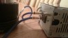
19893825_10208850482691722_149496369_o.jpg
another view

orca-image-1503114909518.jpg_1503114909974.jpeg This is how it looked the final time I had it laid out, this is when the problem got worse and worse.

orca-image-1503114929244.jpg_1503114929660.jpeg This was todays testing, with a newly made antenna driver on bread board, was looking to see if my driver was the problem. This showed its not my driver, Still barely any arc and lots of current draw.

IMG_20170818_211047503.jpg This pic is from today, with new bread board antenna driver. 65v 5.3amps AC. as you can see here its a super weak arc for what I have seen this do.

Could this maybe be that my 470uf 200v storage caps are dead? Maybe one bad sucking my output down. maybe I was seeing it slowly fail since I was finaly pushing this TC?
 

Attachments

  • 19897581_10208850483851751_1006125311_o.jpg
    19897581_10208850483851751_1006125311_o.jpg
    121.7 KB · Views: 105
Alright So I found one issue here for sure!!!!

Before I get to the problem I have found and fixed, lets look at what my waveforms looked like.

20170818210136.png Yellow is antenna signal. Blue is Gate Driver output.----- to me these look pretty well


20170818210421.png This image is my IGBT gate signals... ouch I didnt like this


received_10209141487686665.jpeg Sry this was with my phone, But this is my bridge waveform loaded... ChnYellow GND to one side of my primary and the probe to the other. I noticed the side of my bridge without the DC cap had one massive spike going on.


So I have so far made a new driver, Replaced my MOV's, TV's diodes, GDT, DC Blocking CAP, Power storage caps and rectifier, and my primary. Still has barely any output. This Insane Spike on half my bridge got me worried... I found what it was!!!!


orca-image-1503254364543.jpg_1503254365067.jpeg This..... You can see my GDT in this pic, The green wires are from driver to the GDT primary. I had a ferrite bead on this to help noise. I always had both wires going through but on a different forum I was told to only have one of the two wires wrapped around the bead. Now that I thought of it this cutout problem arose right after i did that. So just for grins I decided to wrap both wires around it again.

20170819234613.png What a difference, WOW. Look at my IGBT gate signals now. I still dont know why its flat on the bottom and slopped on the top.


received_10209141529847719.jpeg Now heres my bridge output loaded.... Spike is gone!!!!! WOW that changed a lot!!! Maybe Matt can explain what happened here..I have no clue but its a ton better...

So even though I cant find a bad IGBT with my multimeter I think that spike fried one, I know from experience it only take 3 working switches on a full bridge to light up, you get a huge reduction in power. So other then my primary those are the only things I have not replaced/ruled out
 
Okay I Found my Problem!!!!!!!!!

I have a clamping RMS AC/DC current meter, I was getting 6.25 amps at about 40VAC on my variac. I then decided to clamp on my primary wire, Only showing 0.75amp... WOW.... Losing 5 amps somewhere.. okay so I changed my IGBT's, Same issue. That leaves two things, My secondary and my gate clamping diodes.. So I looked at my gate waveform again...

So the cause was the fact i took one of the two wires out of the ferrite bead. The failure was my 1.5KE20CA tvs diodes clamping my gate. I'm a retard and didn't look at the voltage on my gate waveform at first, you can see in the sine wave pic I was around 12v. Once I fixed my bead wire, I then got more of a square wave but my voltage was only 8v. You can see the diode conducting, causing the droop on the top of the waveform... ouch.... I had this at 18v So WTH man... Okay de-soldered the TVS diodes and wallla 18.3v Yay!!!!!...

So I take it that my issue was the TVS diodes conducting way to early, This then caused my gate voltage to drop in the linear "ON" region of these IGBT's. All that extra power was being dissipated in the IGBT's. I wasn't detecting any heat since I was only pushing about 2-300Watts, these handle 650w. Overall a bad output dude to the switches not being fully on. Cause was the wire through the ferrite bead, Why?, No clue.... Matt?? LOL

Also Matt, I would still love help with setting the Phase lead Please. and any other suggestions you may have. So, about to put it together and test but I would like your okay on waveforms before I crank above 90VAC.

received_10209146768978694.jpeg
 
So...... I put it all back together, Better, but not fixed. So my output was 8 inch arcs @ 3.5amp AC(Lit @25vac 0.58amp), before I fixed the ferrite wire and the gate TVs diodes I was getting a 1 inch arc @ 6amp AC(Lit 25vac @ 4.5amp). Right now I put it together and am getting 3 inch arcs @ 4.5amp (lit 25vac @ 2.58amp).

So I made progress but not done yet. My guess is as I was trouble shooting, by removing parts or using new ones, is that there is something else pulling current somewhere. I didnt see this because it wasnt the big issue, now that the big problem is fixed maybe I can now find the other part/issue. So Ill most likely start with the TVs diodes and MOVs on the source/drain. If I fried the gate TVs diodes I bet the other might have gone out as well.

When testing this time my gate waveform looks just like my last post. But I now see my bridge output looking a bit different. I think this also may be my Phase lead being way off. I also noticed in the second picture where I have the variac turned up more, I had a 340v pk-pk spike, wow! so about a 170v spike positive, notwmy TVS diodes that protect these transients from causing harm are suppose to start conducting at 205v. I will test tomorrow to make sure those and my MOVs are okay, but now that I have a better scope and can see all this detail now, it should help me tremendously to get rid of these nasty spikes instead of shunting them away.
20170820221608.png

20170820221427.png

20170820221312.png


This image is off Loneoceans QCW DRSSTC 1, he states this is good phase lead so im not sure if mine is bad. but i also dont know where there probing to see the sine wave in yellow.
PaseLeadCorrectHMM.png
 
Last edited:
Hello,

Back from the Teslathon so now I'm able to look at this.

Before doing anything else I really need you to focus on cleaning up your schematic. Forget the troubleshooting right now, get your schematic readable first. Documentation is one of the most useful tools you can have while troubleshooting, so get that done first.

Then I'll ask you to probe a point and post the waveforms, then move on to the next. Right now you're throwing so many copies of the same waveforms at me I can't keep them straight. It's best if we synchronize first, and that requires starting fresh from a clean schematic.

Matt
 
Okay, This is way cleaner. I have troubles drawing the bridge as it should be because I have to draw coils out myself. Let me know if you can read this I made 50 traces not overlap anymore, and re-organised the entire thing.
 

Attachments

  • SSTC3DualGD1.pdf
    114.5 KB · Views: 146
Hello,

Definitely good progress, but still difficult to follow in places. Keep in mind you can use net names and/or sheet-wide connectors, so that you don't have to have wires physically connected everywhere the net goes. For example, for each G-S connection pair that comes off of the GDT, instead of having it connect directly to the IGBT maybe name each pair, like A, B, C, and D. Then draw the H-bridge cleanly and name the pairs A, B, C, and D to match the corresponding GDT connections. Once again, look at other SSTC designs on google and see how others have drawn them, and try to copy it. Also avoid wires going over components because sometimes it's hard to tell where the wire stops and the component outline begins. U5 and U6 are guilty of this, and the wire goes through text. Bad practice there.

You're almost there. Once the schematic is clean and readable I'll print it out and trace it and we can start troubleshooting. I'll give you scope a shot, though I still don't know why you opted for a portable one. You can get a perfectly decent regular scope for the same price.
 
Ya I just like the fact I can take it around, for the price I know I could get a great bench top but I did say I'm okay with spending more for a great portable one. I like not having it referenced, I don't have to worry about probing something and poof lol..

Okay here is A better one, let me know.
 

Attachments

  • SSTC3DualGD2.pdf
    116.3 KB · Views: 114
Matt, If your writing on my schematic of where to probe, could you also let me know some basic settings you would like, some people love persistence some hate it etc...
 
Okay not to confuse you Matt I'm okay with starting from the top but I just found this... My gate input(GDT output) Is Glitching like crazy. I can lessen this glitch as I decrease "ON Time" with my Arduino, as I decrease I see current fall(of course do to less on time) but I can go low enough to where the glitch disappears, when it does I drop almost 2 amps right away! This may be my output reduction problem.

Matt, really not trying to confuse you here. I just know I'm so close, So I want to try what I can. It's all I'm doing today, Want to NAIL IT!
20170821145439.png


This Is when I get rid of glitch and amperage drops like all hell
20170821150743.png


so this guy on 4hv.org (https://4hv.org/e107_plugins/forum/forum_viewtopic.php?144747.30)
He was having the exact looking glitch signal I'm getting. He fixed it by a resistor across bridge?? Took him 3 years to fix it, wow I hope this doesn't take that long..lol


EDIT:
Okay , This isnt a glitch....I think. Its me not knowing how to use my new scope LOL. My modulation pulse doesnt pulse in sync with my ct input. The rise of my modulation pulse triggers in no relation to my input pulse so sometimes it'll switch when my input is high, low, inbetween etc. If i trigger it on the rise of my yellow(gate output sig) it can be right at the start or half way through a pulse width(all depending on where modulation triggers in relation to this input), then causing it to gitter.

If I set this up so my modulation signal is every so many input pulses(in sync) Im sure I would not see this gitter anymore. The reason it looked clean when I lessened my on time was that it fell in sync. weird lol.

So probing some more tomorrow will see what we find
 
Last edited:
What's up guys. Finally decided to Tinker with this thing again. So after all that problem with my current dropping like crazy ended up being my secondary fried on the bottom. I don't know how the hell I missed this. But fixed that and powers back to normal.

DerStorm8
I was wondering if you have ever ran into the problem of your gate drivers heating up extensively. I get about 3 minutes of run time and then my spark starts to slightly pop or fidget. If I turn it off and let them cool down it runs again for three minutes just fine. So I'm pretty convinced it's a heat issue, especially since it runs fine in the beginning but craps out when it gets hot. With my infrared gun it looks like they're getting to about 160°F.

I am now running the Dual 9 amp drivers so I don't think they should be heating up that much. I mean overall it is working great. I just have limited run time. Any thoughts?
The drivers will definitely heat up, especially at higher frequencies and long interrupter pulses. Think I already asked this and didn't get a response (I haven't looked back to double-check though) but can you please post your most up-to-date schematic?
 
Status
Not open for further replies.

Latest threads

New Articles From Microcontroller Tips

Back
Top