Follow along with the video below to see how to install our site as a web app on your home screen.
Note: This feature may not be available in some browsers.
Why are you connecting pin 5 to pin 7 then through a resistor to the negative supply?
You also might want to supply power to the CA3140
The schematic has a 10k pot between pin 1 and pin 5 with the slider of the pot connected to the negative supply.
You have a 10k (or 1k?) fixed resistor between pin 5 and pin 7 and pin 5 is connected to the negative supply.
You don't understand what is a potentiometer. Look it up in Google.
You show a precision trimpot with a screw that turns 10 times or 22 times around. You cannot see where it is adjusted.
I show less expensive but good quality trim pots with an adjustment of about 300 degrees so you can see where it is adjusted.
The middle pin is the slider. Your circuit has an ordinary resistor that does not have a slider.
Good. The offset adjust trimpot is connected correctly.What would we do without google.
I already googled it and thats how i found out that pot was refering to potentionmeter.
Here is an updated drawing.
Good. The offset adjust trimpot is connected correctly.
Thanks.
What about this drawing are they equal?
hi,
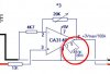
As pointed out by agu,the 10uF are reversed, if you apply 9V to the board they could explode.
Why have you started such a complex project without first getting the basic knowledge regarding components.?
I would suggest if you are interested in building projects you start studying basic electronics.
This is not intended as a 'put down', but doing this project by asking every simple step without understanding each step will not help you to learn.
If you feel you must proceed with this project, forget for the time being the clamp, the AD763 and the PIC and complete the CA3140 amplifier.
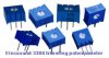
You can use a pot as a mVolt dc test source.
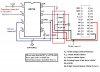
Once you have got that working, program the PIC to read the voltage coming from the CA3140.
hi,
Look at this sketch showing the pots.
Also study the links.
**broken link removed**
Thanks Eric.
Is pin 7 supposed to be pin 6?
Well spotted.! For 7 read 6. Pin 7 is of course +5V.
EDIT:
Dwg error corrected.
hi,
Looked at the pics.
Remember you are working with millivolt level ac signals.
You must keep the interconnecting wires as short as 'reasonable' else you will pick up mains em radiation which will give reading errors.
I would recommend that you build the CA3140 amplifier, this will increase the voltage that is output from the AD736.
You can use your dc meter to check the output.
Use a pot about 10k or 20K as a test input source for the amplifier.
I'll attach a sketch.
I would suggest you try building it on Veroboard, far better than using breadboard - particularly with the massive long wires you've used.