Oh I missed the capacitor part.
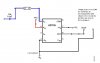
This means that I need to have a capacitor between the sensor and my pin 1?.
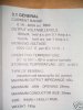
The transformer is just wrapped around one side of the magent, I do not have any specs for it but as in my first post i was able to get some readings regarding the ohms, I do not know if this helps.
Its the details of the current sensor that causing me a little concern.
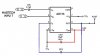
To protect the AD736 it maybe necessary to include some form of voltage clamp on the wire thats going to the capacitor pin 1.
Is the current sensor home made.?
Last edited: