Continue to Site

Welcome to our site!

Electro Tech is an online community (with over 170,000 members) who enjoy talking about and building electronic circuits, projects and gadgets. To participate you need to register. Registration is free. Click here to register now.

  • Welcome to our site! Electro Tech is an online community (with over 170,000 members) who enjoy talking about and building electronic circuits, projects and gadgets. To participate you need to register. Registration is free. Click here to register now.

PCB design help needed. paid!

Status
Not open for further replies.

cda

New Member
Hi all,

What I thought was a simple project has turned into a headache...

Would anyone be interested in designing a simple debounced flip-flop that is always off on initial power on, and changes states with a momentary n/o switch?

Not sure what going rates are for design services, but happy to pay a fair rate.

The purpose is as follows.... we have software video capture program, and we have an external usb switch mapped to start and stop recording via a simple momentary button switch. The rub is that there is no visual feedback that the button has been pushed, eg that recording is happening. Until the software coders get around to a send on start to the usb bus, we can't get feedback out, so we have to fake it by having the same switch toggle an LED at the same time as it toggles the start/stop button in the software.

Having constructed several test circuits posted on various DIY electronics sites, I realize I know too little to make any needed changes to the designs...and we need it sooner than I am likely to learn all I need to know. Hence this post.

Some paramaters:
On power up of the computer, the LED should stay off, and on pushing the momentary button the LED should go on, and go off when the switch is pushed again. Very simple in theory. Not so easy in practice!

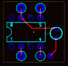
I used this bistable flip-flop **broken link removed** and substituted a resistor for the left hand LED, but it is not reliably "left-handed" on startup. I also added the mentioned 1K resistor in parallel with the LED to make sure it really goes off as the flip-flop changes states. I also added a 1uF capacitor to the base of one of the transistors as was suggested to add a delay and ensure handedness, but it didn't do what was expected and I've run out of experimentation time...I need a circuit that works reliably.

So...the board should be either 5V or 12V, eg power supplied from a standard ATX power supply, preferably 5V via the USB bus. It should have one set of terminals for the LED, one for the switch, and one for power. Otherwise choice of approach (555 IC, 4013 IC, a modified version of the one I tried) is up to you, as long as it does those few things.

Again, the crucial thing is that the LED is off when power is first applied to the system, as it needs to reflect the state of the "start/stop" button in software, which is always off at startup.

thanks!!

Charles
 
It could be done very easy with a 6pin pic

(ive used the 8-pin DIP version because im assuming you dont have access to surface mount tools)

this is a PIC10F200, pin 2 is power, pin 5 is your switch and pin 7 is gnd, just add led and suitable resistor to the other holes.

This is way-overkill for such a simple problem - but if you have the bits lying around why not - its cheap <£1.00 in parts.

The pic obviously needs programmed, but that is a trivial matter for such a simple thing.

There will be MUCH easier ways to do this, but this is at least A solution
 

Attachments

  • ledchip.gif
    ledchip.gif
    10.8 KB · Views: 185
This is MY opinion: The ability to program uC's has become fundamental to electronics.

This problem can be solved with a 53 cent PIC10F200-I/P, bypass cap, switch, led and a resistor. It is no more fair to count the cost of the programmer then it is to count the cost of your soldering tools. :)

But this is, as I said, my opinion. :)

3v0
 
Im in 100% agreement 3v0, and I really must start remembering about things like noise - and include bypass caps in my projects.
 
No PICs, no programming! A simple MAX16054 will do it, too.

And something for PIC freaks: Look out if a circuit is readily available before programming. :D

Boncuk
 
No PICs, no programming! A simple MAX16054 will do it, too.

And something for PIC freaks: Look out if a circuit is readily available before programming. :D

Boncuk

I did say that there were easier ways to do it.

I dont have any MAX16054s in my box, i do however have about 200 different PICs in various pin densities, and any one of them would do this job.

EDIT: Just checked that datasheet. That MAX16054 is surface mount only, therefore more skill to use, and its also 4 times the cost of the pic above. (PIC10F200 = $0.53 / MAX16054 = $2.05)
 
Last edited:
Hmm, well I'll throw in my two cents...

As far as I can see ALL you require is a latch circuit, using flip-flop type things, that is off when first powered? Why not just use CMOS/TLL logic with an RC circuit on the 'reset' line? a CD4013B would do it, plus its cheap.

FlipFlop
Third circuit down :) Its start state when powered up is low. Pretty reliable too. ALso comes with stripboard layout, explaination etc.. you can tell its designed for computer people who are less apt at hardware than software.


If you wish to use a 555 timer:

The link to the page provided
**broken link removed**

Try the 'Relay Toggle Circuit Using a 555 Timer'. Because pin 4 is tied high, it's starting state when powered will be output = low.


I think you're on the right track, if you wish to do it discretely, that is, with transistors, you could use your original circuit but with a few extra components to set its starting state.

Hope this helps, I agree PIC's are a handy solution to anything, but both the above idea's are cheaper. You can't reprogram them, modifying their function, but you only need one fuction right?

Blueteeth

edit:
Like Eric said, where are you? if you're in the UK..guess I could attaempt to knock up a logic circuit/PIC circuit and post it
 
Last edited:
thanks!

Many thanks for all your replies!!

The MAX16054 looks perfect...I'd love to keep experimenting but at this point I need a more or less "out of the box" solution.

Is someone interested in designing a circuit board for this chip to have prototyped? Again, happy to pay a fair rate for your time.

I am located half-time in Amsterdam and half-time in New York, and for the next 3 weeks will be in Amsterdam.

best,

Charles
 
using your MAX chip, for such a very very small circuit you could solder direct to the pins on the chip (or dip socket), or if you dont like that idea, a tiny bit of stripboard available from radioshack, maplin, digikey, mouser etc
 
OOPS just remembered MAX is SMT only, do you have the ability to solder to 'Industry's Smallest Pushbutton On/Off Controller'?
 
In your first post you say the switch is already in your box, is it connected to GND or +5v, as that will determine the layout of the circuit.
 
not sure exactly what you mean, but here's the setup:

we currently have an XPC with the USB bus switch mounted inside...the usb switch board has headers for momentary switches, and +5V/ground pins. So the momentary closes the circuit and the ic on the board sends a mouse click via the USB bus, toggling the start/stop button in software. The idea is that the same momentary switch can be used to toggle the LED to show recording on.

Ideally what I would like is a something that monitors the state of the button in software and then turns the LED on when the state is 'on', but that's a whole other kettle of fish.
 
How many of these are you planning to make? one-off? a thousand?

For a single prototype for a one-off stripboard, and one of the circuits I posted would do. If its for multiple units then obviously the smaller the circuit (and more effective) the better, leaning towards the max chip.

SOT3/6 isn't tough to solder really if you are used to it, but yes you'll need a PCB for it, albeit a tiny one.

Mabye answering the following questions would help others to help you:
1) how many units
2) size requirements
3) manufacturing (depends on number of units, making it yourself? payong for one person to do it? full commercial line?)

An alternative to the max chip would be this:
https://www.electro-tech-online.com/custompdfs/2008/10/doc4771.pdf
Available in DIP08, requires four external components (you can omit two of them if you're just driving an LED). Perfect for prototype board. Also in SOIC08 package if you need it smaller. Not quite as perfect as the MAX solution.

Blueteeth
 
EDIT: Just checked that datasheet. That MAX16054 is surface mount only, therefore more skill to use, and its also 4 times the cost of the pic above. (PIC10F200 = $0.53 / MAX16054 = $2.05)

OK, let's do the math:

MAX16054=$2.05 - ready to use,
PIC10F200=$0.53 - can do nothing.

Assuming progamming time (source code, compiling, burning and veryfying the function) takes 15 minutes if you are superfast. Applying an hourly rate of $150 (extremely cheap) the finished chip will cost $38.03 without charge for the programmer.

This might be acceptable for a unicate. For series production the break even point requires 25 units. (25X$2.05=$51.25, 25X$0.53+$37.50=$50.75)

Additionally soldering a 'THIN SOT23' package with a pin distance of 0.95mm shouldn't require more skill than populating a dense PCB.

Boncuk
 
It didnt sound like a production run, if it was a production run why wouldnt the he just get the 'software guys' he mentioned to fix the software.

As for producing the board - again why would you do a production run of 'mods' youd be better just re-creating the usb interface from scratch to include the required function.

Very expensive pic programming over where you are - id just ask the local college geek if he wants to make a few beer tokens - quite sure he/she could knock up an on/off switch with led by the time id finished asking the question.

Anyway - it would be much easier just to write a systemtray tool that monitors the state of the on-screen button (which if windows is really easy) and output to the led from there. no circuit needed at all just a resistor and led - theres more than one way to skin a cat, as they say.


anyway, back on topic, the switch that is in your box, what pins is it connected to?

the MAX chip uses an active low input, so just wanted to check if it could be connected directly to the max, or if it needs inverted.
 
If Charles is going to do thishe should use whatever he is most comfortable with. If he is going to hire it out that person should do the same. Time
is what counts here and we do best what we know how to do.

With a lot of units the PIC would look better as the unit count
went up because it has less material cost and less PCB footprint.
In the case were the spec is not quite right the uC solution is almost
always easier to fix.

But as pointed out earlier if this was a production
thing it should be fixed in the original product.

3v0
 
Status
Not open for further replies.

Latest threads

Back
Top