Continue to Site

Welcome to our site!

Electro Tech is an online community (with over 170,000 members) who enjoy talking about and building electronic circuits, projects and gadgets. To participate you need to register. Registration is free. Click here to register now.

  • Welcome to our site! Electro Tech is an online community (with over 170,000 members) who enjoy talking about and building electronic circuits, projects and gadgets. To participate you need to register. Registration is free. Click here to register now.

Help needed for 24V Charging w/ Variable Speed Gen

Soul21

Member
Hi All,

I am messing around using pressurized air to charge a bank of 12V lead acid batteries. The batteries are wired for 24V each at 100 Ah. The battery bank powers some small things in a shed (~ 100 watts). The set up I currently have is a Wanco AB30 240V belt driven generator connected to a PSU that cuts and converts voltage from ~230V AC to ~29V DC. That DC is then fed into a MPPT 250 charger which then feeds the batteries. The hydro prime mover is very steady, but will produce different voltage depending on load. Currently I only have the MPPT charge controller set to do a max of 9 amps to avoid the PSU input voltage dropping below 100V.

I tried rectifying the AC to DC and bypass the PSU but the 240VAC turns into 320VDC. The charger controller can only accept up to 250VDC


I have two questions:

  1. I would like to replace the (expensive) PSU with a rectifier and transformer. The rectifier I can figure out, but not sure what an appropriate transformer would be. I found a few 240VAC to 120VAC, but the VA are very small. Ideally I would like to feed 500 W to the batteries when needed.
  2. How would you improve my set up? I think if I were to do it again I would use something closer to a marine 24v alternator instead of the Wanco I have now.

Any help is much appreciated!


parts:
 
I'd look for a multi winding, multi tapped trapped transformer such as this style (but hopefully cheaper!):


That gives you maximum versatility.
Connect all the secondaries in series and use it as an autotransformer - all four in series for 240V in, pick off any voltage along the "chain" of voltage taps.

Or, connect a couple of sections & in phase with the primary for the input, and draw off at the main primary terminals for output - if you added 110V of secondary in series with the primary for input, the "240V" terminals would have around 2/3 the input voltage.


You could also do that with a big, but simpler 230 or240V to 110V transformer, but only ~2/3 input with with series windings or ~half input using primary to secondary.

This would not be too bad, not perfect but cheap!

Input N - 250, output between 100 - 250 would give 60% of input voltage, or output N - 200 for 80% of input.

Add a voltage sense relay to switch taps depending on the generator voltage output??
 
Thanks for the help!

Unfortunately (fortunately) I am going to be pushing at least 20 amps. I would need something closer to 5,000 VA. Still have not found anything that would be a good solution.

Any other recommendations?
 
Apologies. Lack of electronic knowledge.

I did VA based on 20 Amps at 240V. That worked out to 4,800VA. That is pre rectifier and charge controller. The charge controller is currently being fed from the PSU (29VDC) and is feeding 10-20 Amps at 29VDC to the Batteries (580VA max)

Without the PSU could I assumed that pre-rectifier the VA would be similar to what the charger is putting into the batteries? That makes sense to me, but want to double check.

Also, what about no load scenario, when batteries do not need charged? There would be no amps flowing, so the VA would not matter?
 
The charge controller's 99% maximum efficiency spec is pretty much useless. What is important, in your case, is minimum efficiency. If you knew that, you should be able to determine worst case input current draw, which would tell you what size transformer (or, possibly better yet, switching converter) you would need.
I'm guessing that a switching converter would be smaller and cheaper, if you could find a suitable one.
EDIT: If you contact Victron and explain your application, they might be able to help you.
 
Thanks Roff. I have contacted Victron and they have been very helpful, but I still struggle with finding the correct transformer/switching converter.

When you say minimum efficiency do you mean the minimum voltage and amps required to charge the battery? If so, that minimum voltage would be 5V above battery voltage. Taking the 24 volt battery to about 27V when charging. Which means I need about 32V on the charger. As for amps that can be set manually by the charger, but I would say the minimum is 5A in order to be slightly above power draw from the batteries.
 
I might have had some luck!

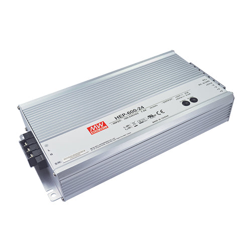
Thoughts on this?

 
Well, here's my thoughts on that:
If your charge controller unit (CCU) can take 48V on the input, puts 20 amps into 48V, and runs at 99% efficiency, then it will only dissipate (24V*20A*1%) 4.8Watts. That means that your HEP-600-48 PSU will only have to deliver (480+4.8) about 489 Watts. That's within the 600W capability of that supply. However, 99% is the maximum CCU efficiency. What if it only runs at 75% efficiency under your operating conditions (I doubt that it will be that low)? That means the supply would have to deliver 600W, which is at the limit of its capability.
Do you see what CCU efficiency means, and why Victron could possibly help you? If you told them you want to charge 24V at 20A, with 48V on its input, they could probably tell you how much input current it requires.
 

Latest threads

New Articles From Microcontroller Tips

Back
Top