Continue to Site

Welcome to our site!

Electro Tech is an online community (with over 170,000 members) who enjoy talking about and building electronic circuits, projects and gadgets. To participate you need to register. Registration is free. Click here to register now.

  • Welcome to our site! Electro Tech is an online community (with over 170,000 members) who enjoy talking about and building electronic circuits, projects and gadgets. To participate you need to register. Registration is free. Click here to register now.

Design simplification for PCB assembly - Need help.

ionBo

New Member
Hi!
First of all, since this is my first post, let me introduce myself. I'm Ben, 37yo, and English is not my first language so I will try to be as specific and precise as I can.

I have no particular knowledge in micro electronics, I try to learn as much as I can, but this time, I'm afraid I can't go further on my project without any help.

My project is a game I made for my kids who love to play indians, with their bow and sticky arrows. I made 10 targets (slaves), using arduinos, shock sensors, LEDs and NRF modules (and the master target with an added bluetooth module), that I spread througout the woods I have in my backyard. The kids run around, hit the targets and try to make the best score... The wireless design allows me to move the targets around and have them fairly spread out if I want to (up to 100 meters).

Here is how it looks, this picture was the first test I did with these (back in 2019), so I put them close together and just checked if everything was working correctly (I was fairly surprised when it did).
targetssetup.png


Here is my issue : I suck at soldering and this project took me weeks to assemble all the components. Also, the more the kids play with it, the more my targets "die" because a wire got loose and it is a real pain to find the issue and fix it. Yesterday, only 6 out of 10 were correctly working...

This is why I come to you with this question : how can I simplify my design as much as possible ?

My objective is to have as few components as necessary, and have a PCB made and all the components pre-assembled/soldered (or as many as possible), to reduce the possibility of poor soldering by myself, and save me time. A lot of time o_O

cablemess.png
cablemess2.png


Here are the components and the use I have of them :
- Arduino nano : it is just the brain, sending commands to other modules. I need a USB access to update the code if I need to.
- NRF24 - 2.4ghz radio module : used to communicate between slaves and master targets.
- SW420 - Shock sensor : detects a hit, sends a signal to the arduino that transmits the info to the NRF24 module
- LED - two colors, common cathode : lights green and red, depending on the game mode.
- JDY-31 - bluetooth module : only present on the master target, used to communicate with a PC (python) or Android (apk).

And this is the wiring :
A = Arduino
BT = JDY-31 BT module (Stat not used)
Shock = SW420 Shock Sensor
LED = Bicolor LED common Cathode
NRF = NRF24L01 (IRQ not used) - I have a 10uF capacitor added, as recommended in a few tutorials


A D6 ⇒ BT TX
A D7 ⇒ BT RX
A D5 ⇒ 220ohm resistor => LED 1
A D3 ⇒ 220ohm resistor => LED 2
A D4 ⇒ Schock DO
A D9 ⇒ NRF CE
A D10 ⇒ NRF CNS
A D11 ⇒ NRF MOSI
A D12 ⇒ NRF MISO
A D13 ⇒ NRF SCK
A 3.3V ⇒ NRF VCC + BT VCC
A 5V ⇒ Shock VCC
A VIN ⇒ Alim Positif
A Ground x2 ⇒ Alim Ground + BT Ground + NRF Ground + LED Ground + Shock Ground

I found tutorials on youtube showing how I could make a standalone arduino, using the chip and a few other components, but for the other modules, I have no idea how to proceed : their schematics are too complex for me and I don't know if I need all their components, for the basic use I have of them. I could maybe succeed with the shock sensor, it seems fairly simple, but I'm lost with the NRF and Bluetooth modules. I am also thinking of a possible improvement, by adding an external antenna to increase range and improve connectivity (trees are often blocking the RF signal, which is understandable considering the NRF module with its integrated antenna is stuck in a small project box, right next to other electronic components...)

Any help and advice with the design would be greatly appreciated!!

Thanks!
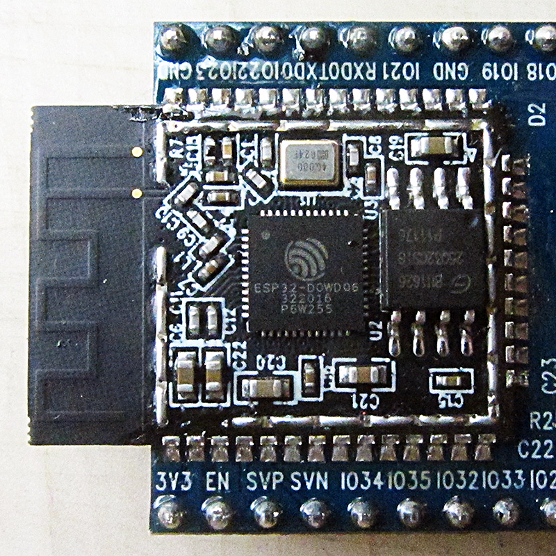
 
If you do design with ESP32 you get WiFi, BT, all in one part/module for
starters. Using the module, vs DIY, avoids the difficulty getting RF layouts
correct. Lots of youtube videos/projects.


A possible alternative to use for development is Tuniot versus Arduino C,
your call. An example of Tuniot use :


Project uses ESP8266, think of it as a lower ended ESP32. It predated the ESP32, and has
been widely accepted like the ESP32.niot handles the ESP32 as well. Focus on that.


Regards, Dana.
 
Last edited:
Stage one is to get a good free PCB design program.

I'd highly recommend "EasyEDA".

Having a quick look in its parts library in the "User contributed" section, there are component listings for various peoples builds of NRF24, SW420 and JDY-31
(And multiple Arduinos / ICs plus thousands of common components of course).
 
danadak : I did look at the esp32 when looking for components on my prototype version. However, I do not need wifi, and bluetooth is only necessary on my master target. I chose the NRF24 module because it allowed bilateral (send/receive) communication between multiple devices at the same time.
- the slave targets need to be connected to the master target, and listen continuously to new data coming their way. They just act according to the 'header' sent in my code that addresses each one of them individually.
- the master target keeps an open connection with all slave targets, in case it needs to send new instructions, and has a bluetooth module to link with a PC or mobile phone, to send/receive instructions from the user.

If i'm not mistaken, i could maybe use the ESP32 in the master target to create a specific wi-fi network, that all slave targets could use to connect to. But the discovery and connecting procedure, along with the communication protocols could be beyond my coding capacities...

Also, the ESP32 is bigger than the Arduino nano. I have "size issues" :joyful: . All components must fit inside a 6x4cm project box. I am trying to keep the electronics footprint as small as possible, hence my call for help/guidance in creating a PCB with all the components integrated. It works well with the modules I am currently using, but I believe I can do smaller and more efficient.
rjenkinsgb : I already did play with EasyEDA and ordered PCBs. However, they just were "plain PCBs", on which I still had to solder my modules. I am looking for a way to have the components directly on the PCB, and have something as simple as possible that could be shipped to me with as little modifications required on my end to make it work.
pcbrouting.png

pcbsetup.png


It works, but the result is...weird. I am not satisfied with that and I feel that plugging the modules is still a waste of time and ressources. I am obsessed with finding a way to end up with a pretty looking PCB with all the components solidly installed and soldered directly onto it, not just plugged on risers.
 
There are two ways to approach this:

1. Make a PCB "mother board" to use existing modules. Put the simple parts like LEDs and stuff on the board directly, and connect the complex modules to the board with header pins. This saves you from a lot of design work, makes the circuit board easy to assemble and probably saves money – those modules often cost less than the parts on the module.

Or.....

2. Do away with some of the modules and duplicate their function on a circuit board. Some modules, like the Arduino probably make no sense to replicate, while others may.

Method 2 is actually practical if you use EasyEDA (available from JLCPCB) and JLC's virtually free assembly service for non-module parts on the board. The limitation of the free assembly service is that you must use components in their system. They have a huge array of parts, but you may have to make some changes in your design.


I helped a startup with a project using method 1. This allowed them to assemble modules onto a circuit board with limited soldering skills, and gave them a marketable product at a good cost. If the product worked out (it did not because of civil war in their country), they could have transitioned to the second method.
 
For The Popcorn : I did option 1 already, but I'm not satisfied with that. I want to try option 2, doing away with the modules themselves.

In my head, all the components would be already there on the PCB. However, i've searched JLCPCB's catalog and identified a few "problems" that I am not technically equipped to answer :
- they sell NRF modules. However, I don't want to deal with a module, I want the components directly on the PCB...
- they don't sell ATMEGA328 chips (the small square one -smd-, or the rectangular one -dip-)

The ATMEGA328 issue : I could buy an arduino equipped with the rectangular ATMEGA chip version, and use it to write/program the firmware into all the chips I will use. On the PCBs themselves, I could easily ask JLCPCB to solder a 28 pin socket. That could even be a nice solution, saving me from installing USB connectors on the PCBs.

I've seen tutorials to get rid of the arduino itself, like the following picture. This is definitely something I want to achieve. And something I want to replicate with the other modules.

1684588814283.png
 
Oh, you posted more details while I was typing

Converting the functionality of some of the modules directly to a printed circuit wouldn't be difficult. The same cannot be said about the rf modules – unless you have a deep understanding of rf design, the chances of success are pretty low.

If you want to proceed, it starts with schematics for all parts of the design.
 
For The Popcorn : well, for the rf design, I was thinking about going the "external antenna" route. I can easily understand the need for very specific knowledge when trying to design an rf antenna directly onto the circuit board :eek:

Plus, an external antenna would be, as I mentionned before, more efficient in my configuration and use case.
I would use something like this on the PCB, a part available on the JLCPCB catalog :

1684589736415.png


For the schematics : getting rid of the arduino is almost a done deal since there are many tutorials available online. Nothing for the shock sensor, the RF and BT modules though.

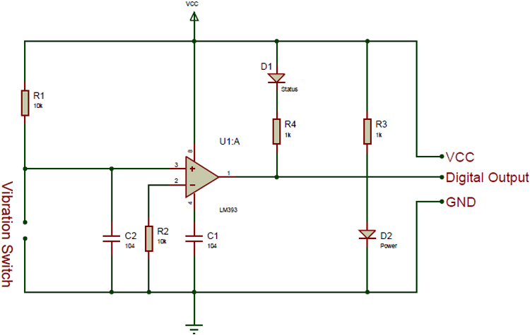
If I take the SW420 schematics, as follows :
Vibrationn-Sensor-Module-Internal-Circuit-Diagram.png


I can understand fairly easily that R1, R2, R3 and R4 are resistors, D1 and D2 are LEDs indicating the status and power state of the circuit. The "Vibration Switch" is also self explanatory. I guess the C1 and C2 are condensators, but "104", I have no idea what stat it refers to.
And... LM393... the triangular shape... I understand this is a chip but how do I connect it ? There are 8 pins on LM393s. Ground and VCC I can find out, but what of the rest ?

I also do not understand why, on the schematic, there are VCC and Ground symbols on top and bottom, when the line is already existing with the pins on the right.

All this to explain how much knowledge I don't have :rolleyes:
 
Last edited:
The shock sensor is easy to do, you can buy the the sensors themselves here:


And the schematic of the modules is a simple comparator, but is shown here:


Easily built-up either through-hole or surface mount.
 
Putting the microcontroller and vibration switch directly on a PCB is straightforward - but I would be very wary of trying to replicate complex RF modules such as the NRF24 or JDY-31

PCB design for RF and especially microwave frequencies is extremely critical and slight errors in layout, even track, width or placing of through-board grounds can seriously mess things up; you could go through many PCB modifications and re-makes before (or without) getting it to work properly.

And, JLCPCB stock the ready-built NRF24 module and will also install that in the PCB, if you include it in the parts list. It's name is WIRELM-SMD_NRF24L01


Having said that, Nordic Semiconductor do provide PCB file and schematics for the modules.

You could use a Gerber file viewer to look at the copper layouts and exactly duplicate those, with the exact components from the parts list - if those are available?

They do stock the IC itself, but it costs more than the ready-built module mentioned above!
 
rjenkinsgb : I was looking at the same thing. The IC costs more than the module itself...
However, there is one thing I learned thanks to you : "JLCPCB stock the ready-built NRF24 module and will also install that in the PCB".
I did not know they did that, I thought they were just providing the module with the PCB, without attaching it to the board. Well, I guess this changes everything. I am keeping the reference (WIRELM-SMD_NRF24L01) close !!

Edit : wow. 2.5$ for the module... They are listed for 0.4$ on Aliexpress :confused:

I will try to draw a schematic with the "standalone arduino" solution and the shock sensor directly on the PCB, and the NRF still as a module, and headers for the JDY-31 (slave and master boards are fairly similar, I don't need BT on the slaves, but if it's just a matter of plugging a module, I can probably live with that).

eTech : I am trying to get rid of the "packaged" modules, as much as I can. The less components, the better, because for me, size matters. If you look at one of my previous posts, I have tried the "risers" option, with an arduino nano and the other modules plugged into the PCB. I have looked at the NANO 33 BLE, the NANO RF... They could be used, but they are one more module on a board and take more space than the actual components I really need.
 
Last edited:
rjenkinsgb : I was looking at the same thing. The IC costs more than the module itself...
However, there is one thing I learned thanks to you : "JLCPCB stock the ready-built NRF24 module and will also install that in the PCB".
I did not know they did that, I thought they were just providing the module with the PCB, without attaching it to the board. Well, I guess this changes everything. I am keeping the reference (WIRELM-SMD_NRF24L01) close !!

Edit : wow. 2.5$ for the module... They are listed for 0.4$ on Aliexpress :confused:

I will try to draw a schematic with the "standalone arduino" solution and the shock sensor directly on the PCB, and the NRF still as a module, and headers for the JDY-31 (slave and master boards are fairly similar, I don't need BT on the slaves, but if it's just a matter of plugging a module, I can probably live with that).

eTech : I am trying to get rid of the "packaged" modules, as much as I can. The less components, the better, because for me, size matters. If you look at one of my previous posts, I have tried the "risers" option, with an arduino nano and the other modules plugged into the PCB. I have looked at the NANO 33 BLE, the NANO RF... They could be used, but they are one more module on a board and take more space than the actual components I really need.
The NANO 33 BLE or IoT has BT and/or NRF functionality on-board (eliminating the external modules) so only one NANO would be needed for the WHOLE UNIT.
 
Some comments about ESP32 :

1) In your slave you have Arduino, RF module, and sensor interface circuit. The ESP32
does all that.

2) You could use just sensor element and have the ESP32 process it, so no external
interface circuit needed like your module SW240 module needs.

2) In your host you add BT, again ESP32 does that as well.

The WiFi, like the NRF24, can implement bidirectional IOT master slave networks, with the appropriate coding.

The above just for future ref since you have already done your coding.


Regards, Dana.
 
IMHO:

“Do away with some of the modules and duplicate their function on a circuit board. Some modules, like the Arduino probably make no sense to replicate, while others may.”

I don’t think it is practical to do this based on your skill level gleaned from this thread. It takes special skills and equipment to test the RF functionality.
 
eTech :
NANO NRF : on the slaves I would still need a shield or some sort of connector to add an LED and the shock sensor.
NANO BLE : used on the master, I would still need to add an LED, the shock sensor and the RF module.

I would skip only one step of the assembly process, and would still be left of with having to manually plug or solder components, which is what I try to avoid as much as possible.

And yes, I will probably have to forget about duplicating the RF and BT modules on a circuit board. But if JLCPCB or any other PCB provider can assemble these modules for me, I will definitely do that.

danadak : thanks for the added info on the ESP32. I will take a closer look at its capabilities and see if it is more interesting costwise. I'm not opposed to updating my code or finding other ways to reach my goal. Coding is easier for me than dealing with electronic stuff...

This is just a pet project for me, something I work on while on holidays, something that helps me learn new things, with the added benefit of creating something my kids and their friends can enjoy... Believe me, having them run around outside all day, instead of them loitering in the house doing nothing, it is a blessing !
 
I think that your schematic for the SW420 has a couple of errors.

See my sketch below:


1684599864432.png


Pin 4 of the LM393 should connect to the 0v line, and C1 should connect to the supply (Vcc)

As drawn it stood no hope of working correctly.

JimB
 
JimB : wow, thanks for the info! When I read your reply, I wanted to compare with other schematics for the shock module and found this one that I like because it adds a potentiometer that could be helpful to adjust the sensitivity

2748-Normally-closed-type-Vibrazione-Sensore-Modulo-alarm-Sensore-Modulo-Vibrazione-Pulsante-SW-420-arduino-compatibile.jpg


Is it any good ?


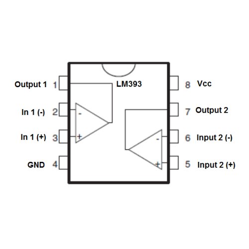
Also, I looked at the LM393 chip and...
ceLM393.jpg

Well, VCC and GND is easy enough. But I don't understand the rest. This chip is supposed to compare the normal voltage and send a signal when it detects a change.
Should I wire the vibration sensor to pins 2 and 2, and use the output 1 ? Is it that simple ?
 
Sounds like you have already created a schematic. I think you'd better design a PCB too. You can use Altium, KiCad of any software you like. Once you create a prototype, you will get idea about scopes for further simplification. you can consider adding an external antenna to the NRF24 modules. You'll need to modify the PCB layout to include an SMA connector for the antenna and ensure the necessary connections are made.

You can get your PCB printed from pcbway. You can also share your design here for further advice
 

Latest threads

New Articles From Microcontroller Tips

Back
Top